A limited range safe recurve bow
A recurve bow and safe technology, applied in bows/crossbows, weapons without explosives, offensive equipment, etc., can solve the problems of poor safety, easy breaking of bow arms, high danger, etc., and achieve the effect of preventing breakage
- Summary
- Abstract
- Description
- Claims
- Application Information
AI Technical Summary
Problems solved by technology
Method used
Image
Examples
specific Embodiment approach 1
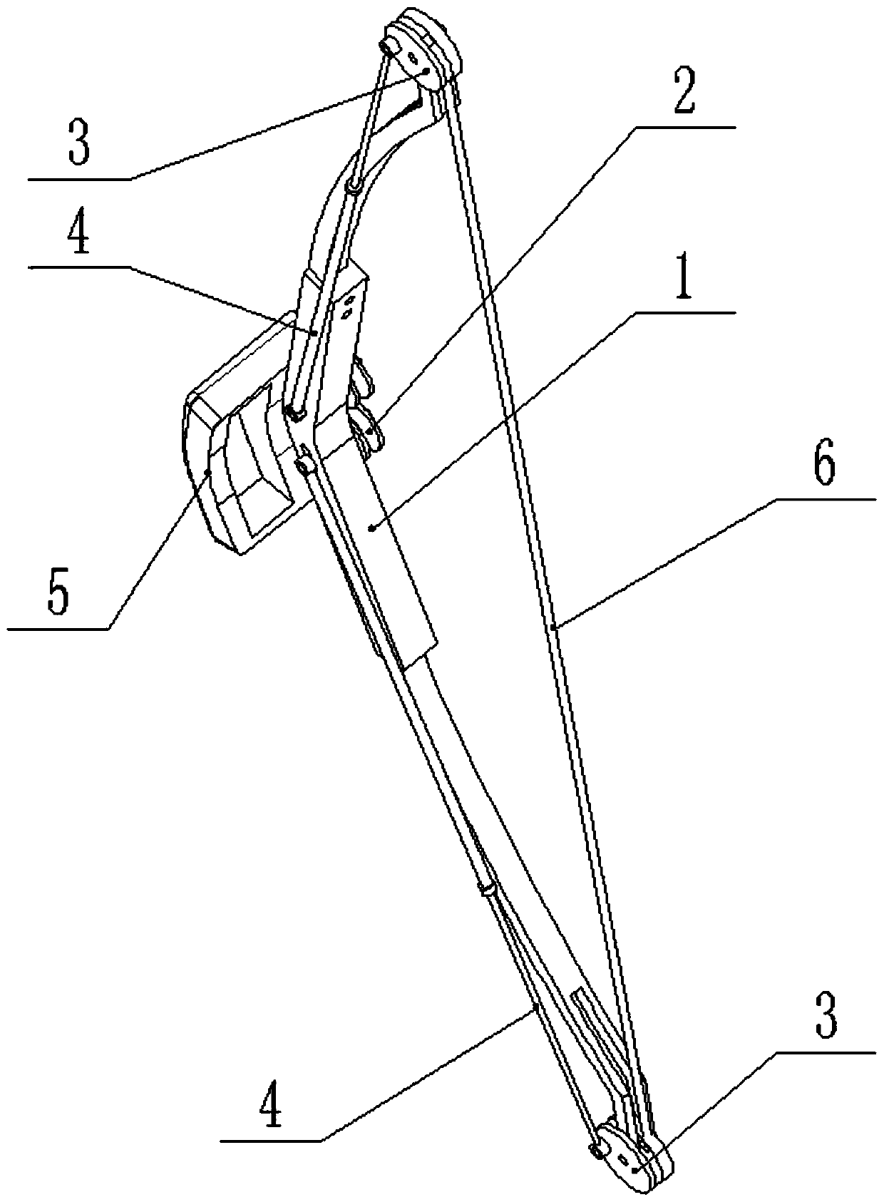
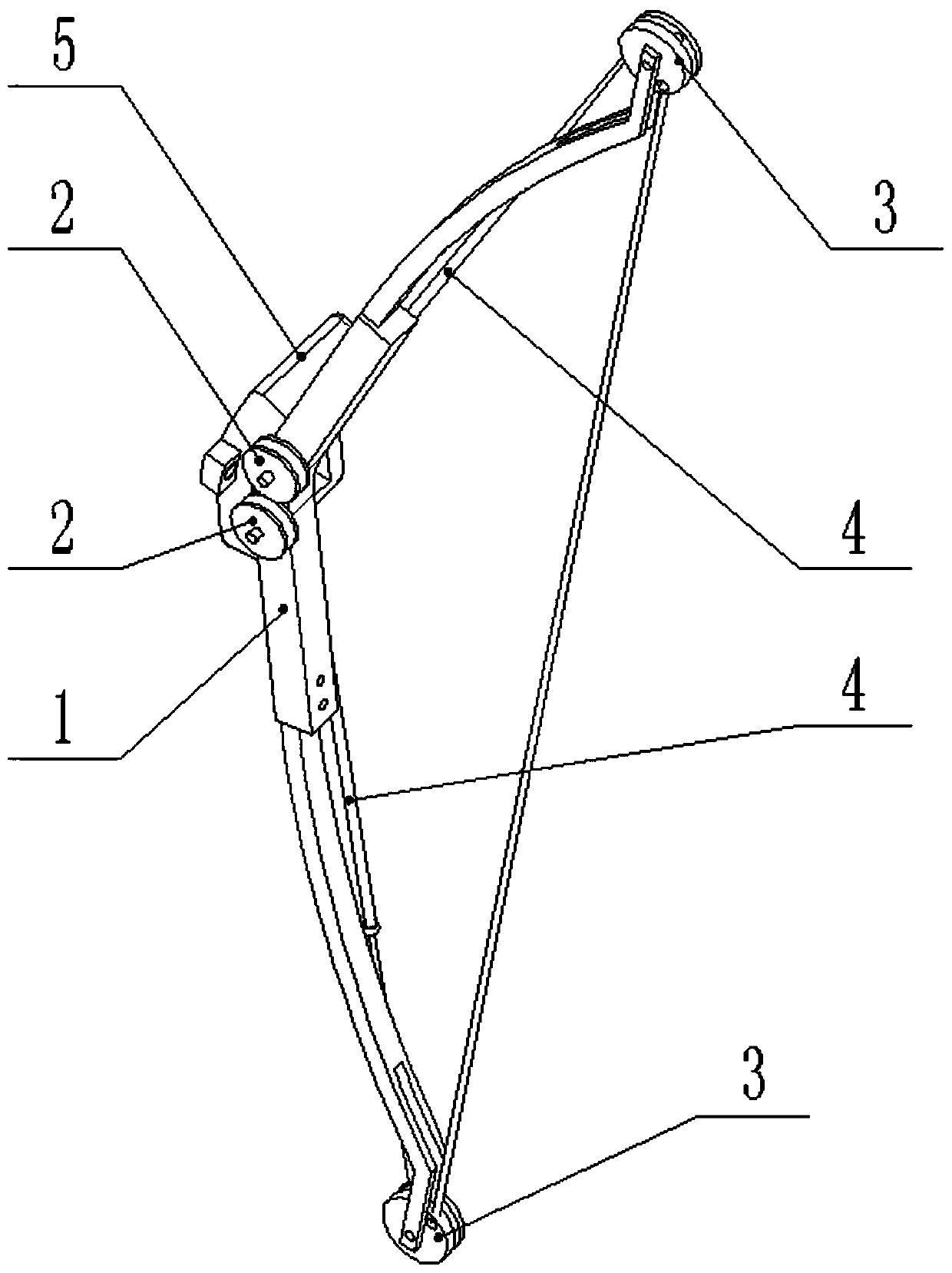
[0026] Combine below Figure 1-9 Describe this embodiment, a limited-range safe recurve bow, including a recurve frame 1, two compression pulleys 2, two articulation wheels 3, two elastic expansion parts 4 and a bow string 6, the recurve frame The middle end of 1 is slidably connected with two compression pulleys 2, and the two ends of the recurve frame 1 are respectively connected with an articulated wheel 3, and one end of the two elastic expansion parts 4 is hingedly connected with the two compression pulleys 2 respectively, The other ends of the two elastic expansion parts 4 are hingedly connected to the eccentric positions of the two articulated wheels 3 respectively, and the two ends of the bow string 6 are respectively connected to the eccentric positions of the two articulated wheels 3; The two ends of 6 drive the two hinged wheels 3 to rotate, and when the hinged wheels 3 rotate, they drive the two elastic expansion parts 4 to squeeze the two compression pulleys 2 tow...
specific Embodiment approach 2
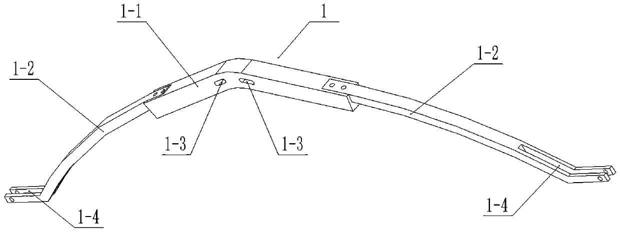
[0028] Combine below Figure 1-9 This embodiment will be described. This embodiment will further describe the first embodiment. The recurve frame 1 includes a handle 1-1 and two elastic bows 1-2, and the two elastic bows 1-2 are respectively connected by bolts. At both ends of the riser 1-1, the middle end of the riser 1-1 is provided with two sliding slots 1-3, and the outer ends of the two elastic limbs 1-2 are provided with hinged wheels for installation. 3 slots 1-4.
specific Embodiment approach 3
[0030] Combine below Figure 1-9 Describe this embodiment, this embodiment will further explain the second embodiment, the pressure pulley 2 includes a sheave 2-1 and a sheave shaft 2-2, and the sheave 2-1 is rotatably connected to the sheave shaft 2-2 Above, the sheave shaft 2-2 is slidably connected in the chute 1-3, and the two ends of the sheave shaft 2-2 are connected with nuts or snap rings, so as to realize the axial positioning of the sheave shaft 2-2.
PUM
 Abstract
Description
Claims
Application Information
 - R&D Engineer
- R&D Manager
- IP Professional
- Industry Leading Data Capabilities
- Powerful AI technology
- Patent DNA Extraction
Browse by: Latest US Patents, China's latest patents, Technical Efficacy Thesaurus, Application Domain, Technology Topic, Popular Technical Reports.
© 2024 PatSnap. All rights reserved.Legal|Privacy policy|Modern Slavery Act Transparency Statement|Sitemap|About US| Contact US: help@patsnap.com


