
A method for locating the position of railway line sleepers

A technology for railway lines and positioning methods, which is applied to roads, tracks, track maintenance, etc., can solve the problems of large operation errors, unstable operation status, and low degree of automation, and achieves small operation errors, no manual intervention, and high degree of automation. Effect

Active Publication Date: 2020-01-31
ZHUZHOU TIMES ELECTRONICS TECH CO LTD
View PDF7 Cites 0 Cited by
  • Summary
  • Abstract
  • Description
  • Claims
  • Application Information

AI Technical Summary

Problems solved by technology

[0006] In view of this, the object of the present invention is to provide a method for locating the sleeper position of railway lines, so as to solve the technical problems of existing railway line sleeper position measurement methods, such as large operating errors, low degree of automation, unstable operating conditions, and manual intervention.

Method used


Image

  • A method for locating the position of railway line sleepers
  • A method for locating the position of railway line sleepers
  • A method for locating the position of railway line sleepers

Examples


Embodiment 1

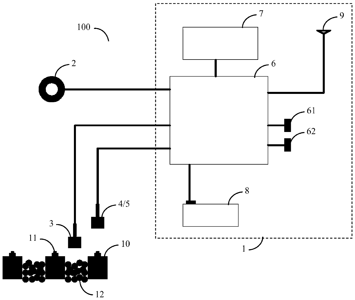
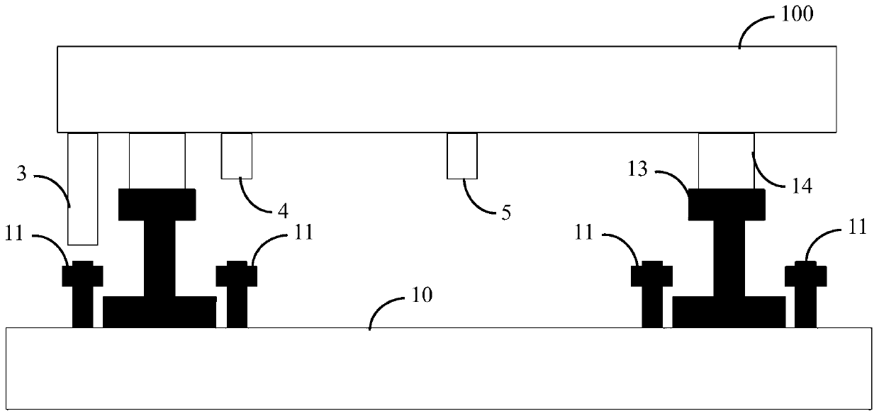
[0043] as attached figure 1 And attached figure 2 As shown, a specific embodiment of the railway line sleeper position measuring device based on the method of the present invention includes:

[0044] Measurement module 1;

[0045] The measuring wheel 2 connected with the measuring module 1 is used to measure the mileage of the railway line;

[0046] The magnet induction switch 3 connected with the measurement module 1 is used to detect the spike 11 on the sleeper 10;

[0047] The first distance proximity switch 4 connected with the measurement module 1 is used to detect the spike 11 on the sleeper 10;

[0048] The second distance proximity switch 5 connected with the measuring module 1 is used for detecting the sleeper 10 .

[0049] The railway line sleeper position measuring device 100 is placed (supported by the wheel set 14) on the rail 13, the magnetic induction switch 3 measures the spike 11 on the sleeper 10, the first distance proximity switch 4 measures the spike ...

Embodiment 2

[0060] as attached Figure 7 As shown, a specific embodiment of the railway line sleeper position positioning method of the present invention comprises the following steps:

[0061] S101) When located at the starting point of the railway line, the railway line sleeper position measuring device 100 will mark the kilometer to the starting point;

[0062] S102) The railway line sleeper position measuring device 100 begins to measure along the railway line, and the kilometer mark moves forward. When the sleeper 10 is detected, the center position of the sleeper 10 is marked, and the corresponding kilometer mark is marked;

[0063] S103) When it is detected that there is an obstacle 16 between the sleepers 10, an obstacle mark is marked between the two sleepers 10, and a corresponding kilometer mark is marked;

[0064] S104) When it is detected that there is a joint 17 between the two rails 13, a rail joint mark is marked between the corresponding two sleepers 10, and the correspo...


PUM


Abstract

The invention discloses a positioning method of a railway line sleeper position. The method includes steps of positioning a kilometer post at a starting point by a position measuring device of the railway line sleeper when it is located at the starting point of the railway line; measuring along the railway line by the position measuring device of the railway line sleeper, making the kilometer postmove forwards; when the sleeper is detected, marking the center of the sleeper and marking corresponding kilometer post; when an obstacle existed between sleepers is detected, labeling an obstacle mark between two sleepers, and marking corresponding kilometer post; when a joint between the two steel rails is detected, labeling a steel rail joint mark between two corresponding sleepers, and marking corresponding kilometer post; when the position measuring device of the railway line sleeper carries out continuous detection until the measurement of the railway line is finished, forming a data file of the corresponding relationship between the sleeper and the kilometer post. The positioning method can solve the technical problems of big working bias, low automatic degree, unstable working state, manual interference of the existing measurement methods.

Description

technical field [0001] The invention relates to the field of railway engineering measurement, in particular to a method for locating the position of railway line sleepers. Background technique [0002] During the automatic tamping operation of large-scale road maintenance machinery, it is usually necessary to measure the working railway line first, so as to calculate the position of the tamp pick. Within the moving distance from the current position to the next tamping and lowering position, if there are other equipment or obstacles in the middle of some line sleepers, the tamping and lowering operation cannot be performed at this position, but should be avoided. Moreover, at the joints of the rails, the line is prone to settlement, so it is usually necessary to increase the number of times of tamping during the actual tamping operation. [0003] At present, the maintenance of railway lines has changed from the manual method to the large-scale construction machinery method....

Claims


Application Information

Patent Timeline
Patent Type & Authority Patents(China)
IPC IPC(8): E01B35/02
CPCE01B35/02
Inventor 言建文刘振军陈聪徐靖张先明兰升戴海仙曹康军余志强王嵘周军侯仁军彭国平
Owner ZHUZHOU TIMES ELECTRONICS TECH CO LTD
Learn More