
Fixed foot pad swivel chair

A technology of foot pads and swivel chairs, applied in the field of swivel chairs, can solve the problems of difficulty in matching foot pads, overall aesthetic impact, and high cost, and achieve the effects of low cost, beautiful appearance, and reasonable structure

Pending Publication Date: 2018-05-29
AURORA CHINA
View PDF5 Cites 0 Cited by
  • Summary
  • Abstract
  • Description
  • Claims
  • Application Information

AI Technical Summary

Problems solved by technology

[0002] A swivel chair is a chair that can be rotated while sitting. Due to its user-friendly design, it has become more and more standard equipment for office chairs. It is distinguished by mobility. Swivel chairs can be divided into movable swivel chairs and non-movable swivel chairs. The mobile swivel chair is generally moved by the universal wheels set at the bottom of the chair, and it is widely used. However, in some occasions where the chair is not suitable for moving, the non-movable swivel chair has an irreplaceable role. The bottom of the general non-movable swivel chair is provided with foot pads The bottom of the foot pads of some high-end chairs is also equipped with rubber pads to cushion and eliminate noise, but generally the rubber pads are glued to the bottom of the foot pads through adhesives, or made into one with the foot pads, and glued to the feet. The rubber pad at the bottom of the pad will fall off with the prolongation of use time or improper use. When the rubber pad integrated with the foot pad is worn out, it can only be replaced together with the foot pad. When replanting floor mats, it is difficult to match the same floor mats as the original ones. Replacement with different floor mats will have a great impact on the overall appearance

Method used


Image

  • Fixed foot pad swivel chair
  • Fixed foot pad swivel chair
  • Fixed foot pad swivel chair

Examples


Embodiment 1

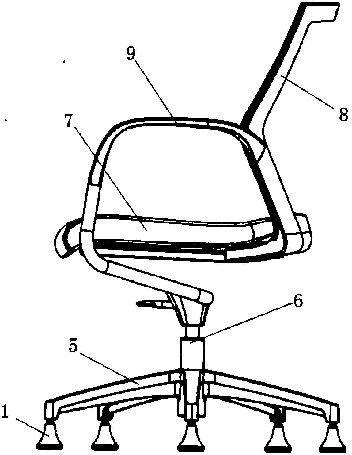
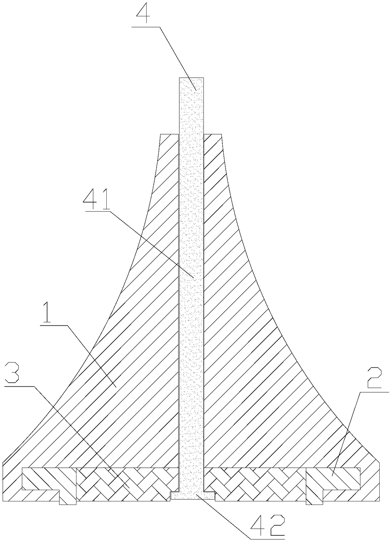
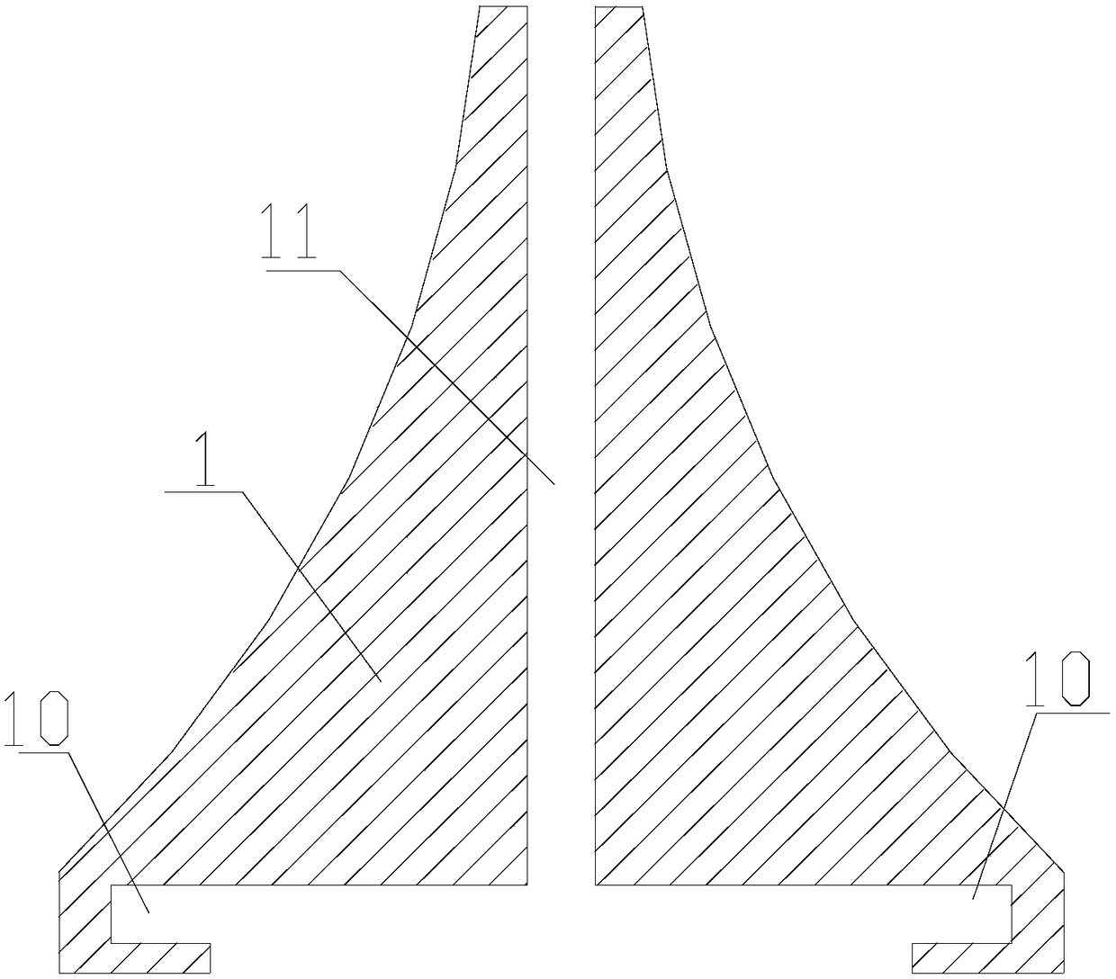
[0024] A swivel chair with fixed feet, such as figure 1 As shown, it includes a swivel chair body and foot pads. The preferred swivel chair body in this embodiment includes a base 5, a lifting rod 6, and a seat surface 7 connected sequentially from bottom to top. The seat surface 7 is provided with a seat back 8 and an armrest 9. At the bottom of the base 5 , the present embodiment selects a five-star base as the base 5 . The foot pad includes a fixed rod mechanism, a foot pad body 1 and a rubber ring 2, such as figure 2 with 3 As shown, the fixed rod assembly includes a fixed rod 4 and a baffle 3. The foot pad body 1 and the baffle 3 are provided with a vertically penetrating fixed rod hole 11. In this embodiment, the foot pad body 1 is preferably trumpet-shaped, and the foot pad body The bottom is provided with a "convex" hole with an inverted shaft section. The part of the hole located in the foot pad body cooperates with the foot pad body to form an annular groove 10. T...

Embodiment 2

[0026] This embodiment is basically the same as Embodiment 1, except that the bottom surface of the baffle plate 3 in this embodiment is provided with a recess for accommodating the head 42 of the fixing rod.


PUM


Abstract

The invention relates to a fixed foot pad swivel chair comprising a swivel chair body and foot pads, wherein each foot pad comprises a fixing rod mechanism, a foot pad body (1) and a rubber ring (2),the rubber ring (2) is arranged on the bottom of the foot pad body (1), the fixing rod mechanism penetrates the foot pad body (1) to fix the foot pad on the bottom of the swivel chair body, the bottomof the foot pad body (1) is provided with a hole with an inverted-convex-shaped axial cross section, one part, located in the foot pad body, of the hole is matched with the foot pad body to form an annular groove (10), the rubber ring (2) comprises an engaging portion (21) with an annular cross-section and a flange (22) disposed on the bottom surface of the engaging portion (21), the engaging portion (21) is filled in the annular groove (10), and the flange (22) protrudes from the bottom surface of the foot pad body (1). Compared with the prior art, the fixed foot pad swivel chair has the advantages of long service life, convenient replacement of the rubber pads, beautiful appearance of the foot pads, and the like.

Description

technical field [0001] The invention relates to a swivel chair, in particular to a swivel chair with fixed foot pads. Background technique [0002] A swivel chair is a chair that can be rotated while sitting. Due to its user-friendly design, it has become more and more standard equipment for office chairs. It is distinguished by mobility. Swivel chairs can be divided into movable swivel chairs and non-movable swivel chairs. The mobile swivel chair is generally moved by the universal wheels set at the bottom of the chair, and it is widely used. However, in some occasions where the chair is not suitable for moving, the non-movable swivel chair has an irreplaceable role. The bottom of the general non-movable swivel chair is provided with foot pads The bottom of the foot pads of some high-end chairs is also equipped with rubber pads to cushion and eliminate noise, but generally the rubber pads are glued to the bottom of the foot pads through adhesives, or made into one with the ...

Claims


Application Information

Patent Timeline
Patent Type & Authority Applications(China)
IPC IPC(8): A47C7/00A47C3/18A47C3/20
CPCA47C3/18A47C3/20A47C7/004
Inventor 姚辉张巍
Owner AURORA CHINA
Learn More