
Pesticide spray device for garden plants

A plant and garden technology, applied in the field of garden plant spraying devices, can solve the problems of uneven stirring, human injury, low degree of automation, etc., and achieve the effects of reducing manual operation, improving work efficiency, and improving automation control rate.

Inactive Publication Date: 2018-05-29
广州天品科技有限公司
View PDF1 Cites 2 Cited by
  • Summary
  • Abstract
  • Description
  • Claims
  • Application Information

AI Technical Summary

Problems solved by technology

The widely used sprinklers mainly include manual sprayers and mechanically driven sprayers. The manual sprayer is attached to the body for manual spraying, which is time-consuming and laborious, and the spraying effect is general; The pesticides in the tank are often mixed unevenly. At the same time, due to the precipitation characteristics of the pesticides themselves during the long-term spraying process, it is easy to cause the pesticides to not be fully mixed, and the requirements for uniform spraying cannot be achieved; while the existing mechanized sprayers have a relatively complicated structure. The price is expensive and the degree of automation is not high, resulting in low efficiency of pesticide spraying and increasing the chance of contact between people and pesticides, thus causing harm to the human body during pesticide spraying

Method used


Image

  • Pesticide spray device for garden plants
  • Pesticide spray device for garden plants
  • Pesticide spray device for garden plants

Examples


Embodiment Construction

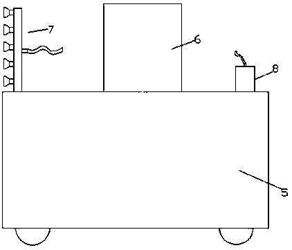
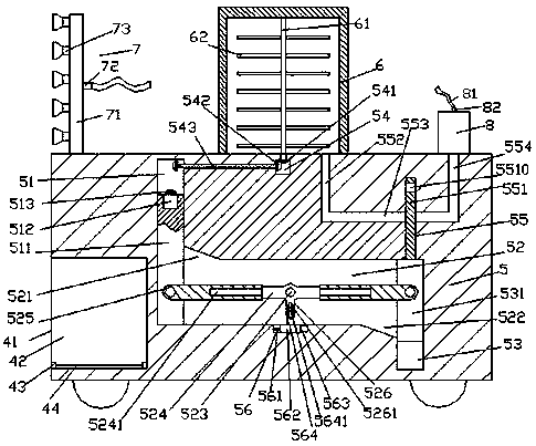
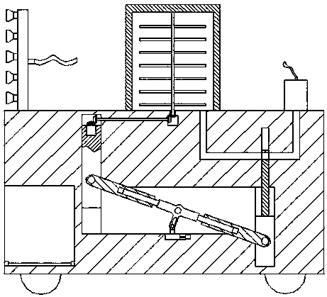
[0023] Such as Figure 1-Figure 4As shown, a garden plant spraying device of the present invention includes a spraying car body 5 and a spraying box 6 installed on the top of the spraying car body 5, and the spraying box 6 directly below the spraying box 6 The car body 5 is provided with a first cavity 54, the top wall of the first cavity 54 is rotatably connected with a first cone wheel 541, and the top of the first cone wheel 541 is fixed with an upwardly extending section that runs through the first The inner top wall of a cavity 54 and the stirring shaft 61 that is connected by rotation, the spraying vehicle body 5 below the first cavity 54 is provided with a second cavity 52 extending left and right, and the second cavity The left extension end of the body 52 is connected with a first sliding cavity 51 extending upwards. A first rotating shaft 543 extending left and right is connected between the inner wall on the left side of the body 54 and the inner wall on the right ...


PUM


Abstract

The invention discloses a pesticide spray device for garden plants. The pesticide spray device comprises a pesticide spray vehicle body and a pesticide spray box mounted at the top of the pesticide spray vehicle body; a first cavity is arranged directly below the pesticide spray box and in the pesticide spray vehicle body; the inner top wall of the first cavity is in rotatable matched connection with a first conical wheel; the top of the first conical wheel is fixedly provided with a stirring shaft, wherein an upward extension section of the stirring shaft passes through the inner top wall ofthe first cavity and is in rotatable matched connection with the inner top wall of the first cavity; a second cavity extending left and right is arranged below the first cavity and in the pesticide spray vehicle body; the left extension end of the second cavity communicates with a first sliding cavity arranged in a way of extending upwards; a top extension section of the first sliding cavity is located on a position opposite to the left side of the first cavity; and a first rotating shaft which is arranged in a way of extending left and right is rotatably connected between the inner wall at the left side of the first cavity and the inner wall at the right side in the top extension section of the second cavity in a matched way. The pesticide spray device is simple in structure, convenient to operate, long in service life, high in automation degree, capable of increasing the work efficiency of pesticide spray, improving the pesticide spray quality and avoiding human injury during pesticide spray and high in safety.

Description

technical field [0001] The invention relates to the technical field of agricultural machinery, in particular to a garden plant pesticide spraying device. Background technique [0002] During the growth of crops, due to pests or other reasons, pesticides need to be sprayed frequently to promote their growth. The widely used sprinklers mainly include manual sprayers and mechanically driven sprayers. The manual sprayer is attached to the body for manual spraying, which is time-consuming and laborious, and the spraying effect is general; The pesticides in the tank are often mixed unevenly. At the same time, due to the precipitation characteristics of the pesticides themselves during the long-term spraying process, it is easy to cause the pesticides to not be fully mixed, and the requirements for uniform spraying cannot be achieved; while the existing mechanized sprayers have a relatively complicated structure. The price is expensive, and the degree of automation is not high, re...

Claims


Application Information

Patent Timeline
Patent Type & Authority Applications(China)
IPC IPC(8): A01M7/00
CPCA01M7/005A01M7/0082
Inventor 潘云江
Owner 广州天品科技有限公司
Learn More