
Shearing box for testing shearing anisotropy of structural surface of rock body

An anisotropic, shear box technology, applied in the direction of using a stable shear force to test the strength of materials, can solve problems such as insufficient research results on shear strength anisotropy

Pending Publication Date: 2018-05-25
INST OF GEOLOGY & GEOPHYSICS CHINESE ACAD OF SCI
View PDF7 Cites 11 Cited by
  • Summary
  • Abstract
  • Description
  • Claims
  • Application Information

AI Technical Summary

Problems solved by technology

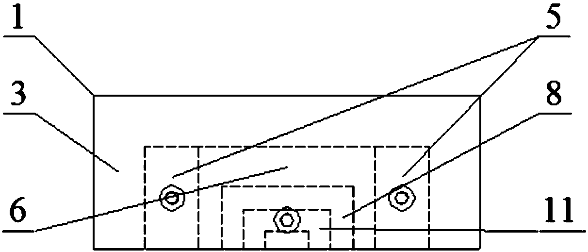
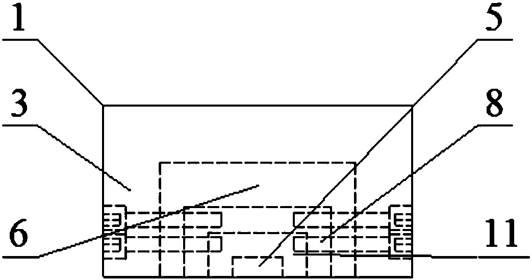
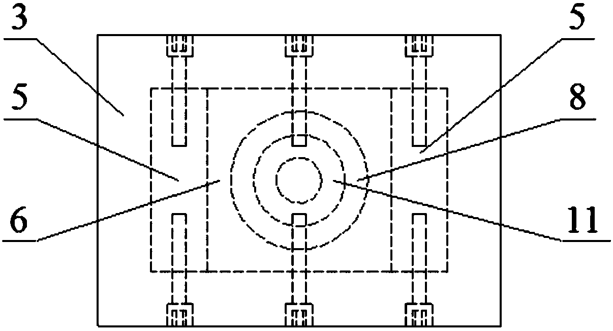
[0005] In order to solve the above-mentioned problems in the prior art, that is, in order to solve the problem of insufficient research results on the shear strength anisotropy of rock mass structural planes with different shapes and scales, the present invention provides a method for testing the shear strength of rock mass structural planes. Cutting an anisotropic shearing box, the shearing box includes an upper shearing box and a lower shearing box arranged oppositely, and the upper shearing box and the lower shearing box all include an outer box, an inner cylinder and a set An adjustment assembly between the outer box and the inner cylinder, an accommodating cavity for placing the rock mass to be tested is formed between the upper shear box and the inner cylinder of the lower shear box, wherein the upper The outer box, the inner cylinder and the adjustment assembly in the shear box are fixedly connected, and at least the inner cylinder in the lower shear box can rotate relative to the outer box

Method used


Image

  • Shearing box for testing shearing anisotropy of structural surface of rock body
  • Shearing box for testing shearing anisotropy of structural surface of rock body
  • Shearing box for testing shearing anisotropy of structural surface of rock body

Examples


Embodiment Construction

[0048] Those skilled in the art should understand that the embodiments in this section are only used to explain the technical principle of the present invention, and are not used to limit the protection scope of the present invention. For example, although the fixed or mutual rotation between the parts is described in combination with square and circular shapes in the accompanying drawings, this is not static, and those skilled in the art can make adjustments to it as needed so as to adapt to specific conditions. In application occasions, such as replacing a square shape with an irregular special-shaped structure, etc., obviously, the adjusted technical solution will still fall within the scope of protection of the present invention.

[0049] It should be noted that, in the description of the present invention, the terms "center", "upper", "lower", "left", "right", "front", "rear", "inner", "outer" and the like indicate The terms of direction or positional relationship are bas...


PUM


Abstract

The invention belongs to the technical field of indoor experiments of rock mass mechanics, in particular provides a shearing box for testing shearing anisotropy of a structural surface of a rock body,and aims to solve the problem that research results of shearing strength anisotropism of structural surfaces of rock bodies of different shapes and different scales are insufficient. The shearing boxprovided by the invention comprises an upper shearing box and a lower shearing box, wherein both the upper shearing box and the lower shearing box comprise outer boxes, adjusting plates, outer cylinders, adjusting cylinders and inner cylinders; an accommodation cavity for holding a rock body to be tested is formed between inner cylinders of the upper shearing box and the lower shearing box; the outer box, the adjusting plate, the outer cylinder, the adjusting cylinder and the inner cylinder of the upper shearing box are fixedly connected through bolts; at least the inner cylinder of the lowershearing box can be rotated for any angle relative to the outer box. Therefore, by changing outer cylinders, adjusting cylinders and / or inner cylinders of different shapes and sizes, shearing testingon structural surfaces of different shapes and sizes in any shearing direction can be directly implemented by using the shearing box provided by the invention.

Description

technical field [0001] The invention belongs to the laboratory field of rock mechanics, and specifically provides a shear box for testing the shear anisotropy of rock mass structural planes. Background technique [0002] Rocks are composed of individual minerals or debris under certain geological processes and according to certain rules to form aggregates with certain connection functions. Rocks are components of rock mass. The major difference between rock mass and general objects is that it is cut vertically and horizontally by structural planes and has multiple fractures with a certain structure. The deformation and strength of rock mass are controlled by structural planes, so how to accurately grasp the mechanical properties of structural planes, especially the shear deformation and strength properties, is the key to evaluating the stability of engineering rock mass. The indoor experiment of rock mechanics is an important way to study the shear deformation and strength ...

Claims


Application Information

Patent Timeline
Patent Type & Authority Applications(China)
IPC IPC(8): G01N3/24
CPCG01N3/24
Inventor 祁生文郑博文郭松峰黄晓林邹宇梁宁马丽娜
Owner INST OF GEOLOGY & GEOPHYSICS CHINESE ACAD OF SCI
Learn More