
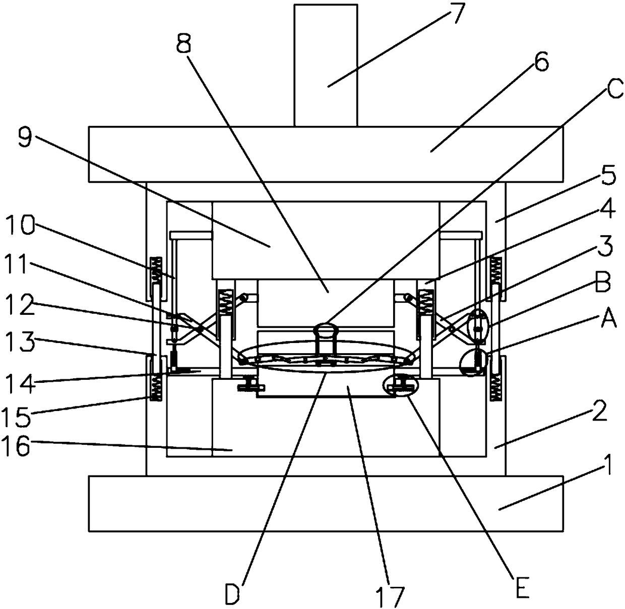
Stamping and hole flanging device

A technology of turning holes and linkage devices, which is applied in the field of stamping dies, can solve the problems of reduced production efficiency and increased mold costs, and achieve the effects of saving production, improving work efficiency, and avoiding secondary operations

Active Publication Date: 2018-05-22
MAANSHAN WANXIN CASTING
View PDF9 Cites 4 Cited by
  • Summary
  • Abstract
  • Description
  • Claims
  • Application Information

AI Technical Summary

Problems solved by technology

[0002] At present, the traditional mode of turning holes in the machinery industry is basically to directly transmit the downward pressure generated by the press to the parts to be turned through the machine, and use the mold to act on the sheet metal parts to realize the parts turning holes. The hole is generally turned downward from the upper surface of the part. If the hole is turned upward from the surface of the part, the sheet metal part must be placed on a floating mold, and the hole turning punch is fixed on the lower mold base. Under the downward pressure of the press , the sheet metal part moves downward together with the floating part of the mold, and the hole turning punch relatively moves upward and acts on the sheet metal part to finally realize the hole turning operation, and if the upper surface of the sheet metal part needs to be stretched, folded, and other multi-process operations At the same time, the lower surface of the sheet metal part needs to be turned upwards. The traditional stamping process cannot be realized through one-time mold loading, but requires secondary mold loading. At the same time, the mold should be designed into two sets. In this way, Not only the mold cost is increased, but the production efficiency is also greatly reduced

Method used


Image

  • Stamping and hole flanging device
  • Stamping and hole flanging device
  • Stamping and hole flanging device

Examples


Embodiment Construction

[0021] The following will clearly and completely describe the technical solutions in the embodiments of the present invention with reference to the accompanying drawings in the embodiments of the present invention. Obviously, the described embodiments are only some, not all, embodiments of the present invention.

[0022] In describing the present invention, it should be understood that the terms "upper", "lower", "front", "rear", "left", "right", "top", "bottom", "inner", " The orientation or positional relationship indicated by "outside", etc. is based on the orientation or positional relationship shown in the drawings, and is only for the convenience of describing the present invention and simplifying the description, rather than indicating or implying that the referred device or element must have a specific orientation, so as to Specific orientation configurations and operations, therefore, are not to be construed as limitations on the invention.

[0023] refer to Figure ...


PUM


Abstract

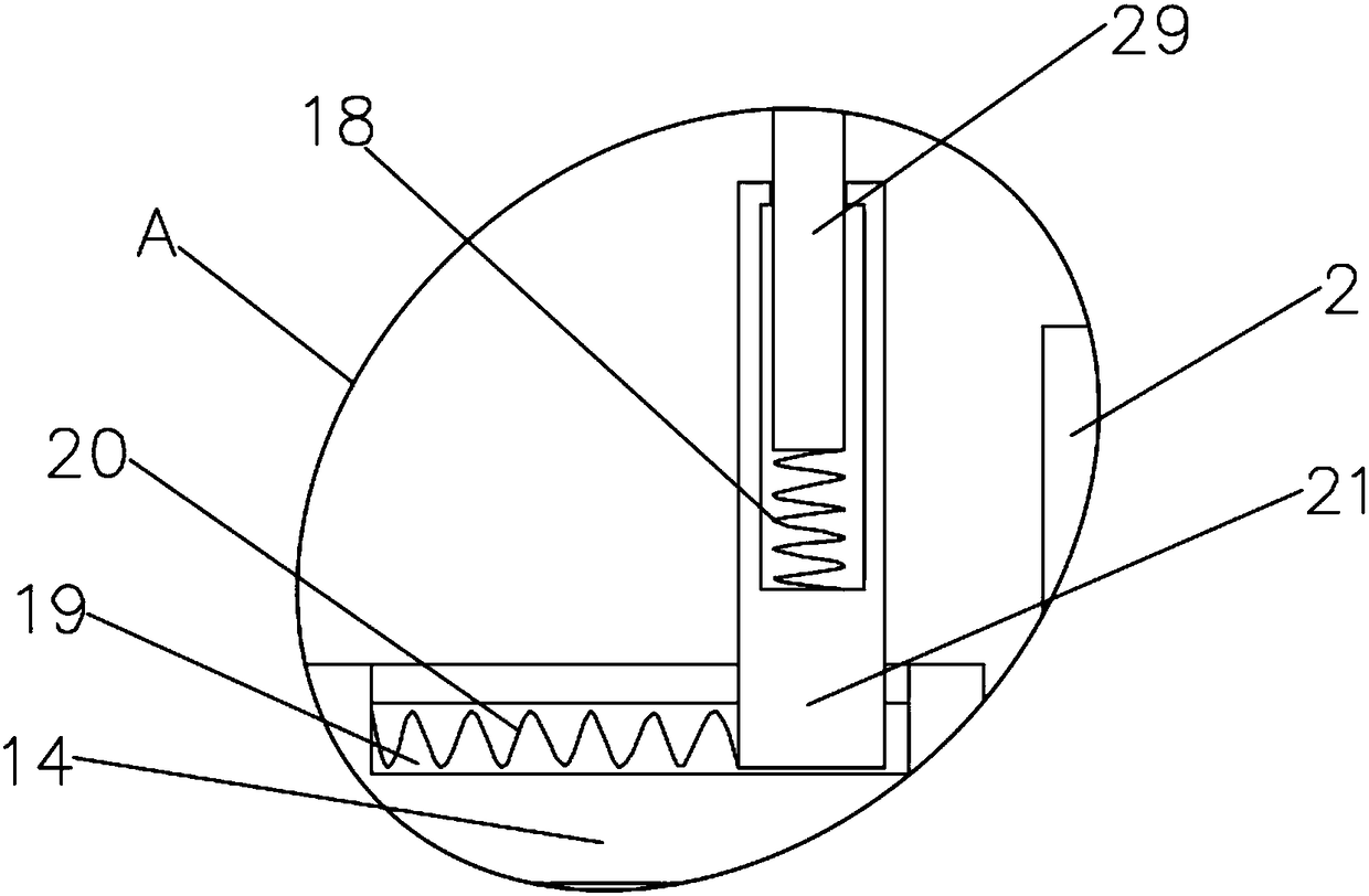
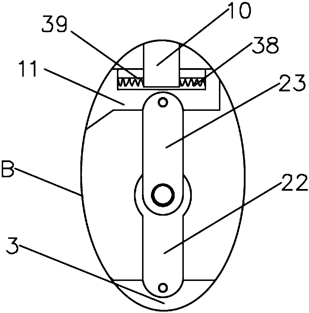
The invention discloses a stamping and hole flanging device. The stamping and hole flanging device comprises a first pressing block and a second pressing block, the second pressing block is arranged at the bottom of the first pressing block, and the end, away from the first pressing block, of the second pressing block is provided with a first fixing body. A base is arranged at the bottom of the first fixing body, a groove is formed in the first fixing body, and the second pressing block is inserted on the groove. Clamping devices are symmetrically arranged on the two sides of the groove, the second pressing block is fixedly connected to the groove through clamping devices, and the end, away from the second pressing block, of the first pressing block is fixedly connected with a second fixing body. The upper portion of the second fixing body is provided with a top seat, and the top seat is connected with an oil cylinder. According to the stamping and hole flanging device, operation is easy, through mutual cooperation of the clamping devices, a movable device, a connecting device, a linkage device and an adjusting device, the two sides of a metal sheet can be stamped simultaneously, secondary operation is avoided, the work efficiency can be improved while the production cost is saved, and the stamping and hole flanging device is provided for a user.

Description

technical field [0001] The invention relates to the technical field of punching dies, in particular to a punching hole turning device. Background technique [0002] At present, the traditional mode of turning holes in the machinery industry is basically to directly transmit the downward pressure generated by the press to the parts to be turned through the machine, and use the mold to act on the sheet metal parts to realize the parts turning holes. The hole is generally turned downward from the upper surface of the part. If the hole is turned upward from the surface of the part, the sheet metal part must be placed on a floating mold, and the hole turning punch is fixed on the lower mold base. Under the downward pressure of the press , the sheet metal part moves downward together with the floating part of the mold, and the hole turning punch relatively moves upward and acts on the sheet metal part to finally realize the hole turning operation. If the upper surface of the sheet...

Claims


Application Information

Patent Timeline
Patent Type & Authority Applications(China)
IPC IPC(8): B21D19/08
CPCB21D19/088
Inventor 张立安魏明军
Owner MAANSHAN WANXIN CASTING
Learn More