
Cable deconcentrator

A splitter and cable technology, applied in circuit/collector parts, electrical components, circuits, etc., can solve the problems of reducing radar system performance, cluttered cables, and time-consuming, etc., to achieve simple structure and easy use. Flexibility, longevity effect

Pending Publication Date: 2018-05-18
XTR SOLUTIONS
View PDF0 Cites 0 Cited by
  • Summary
  • Abstract
  • Description
  • Claims
  • Application Information

AI Technical Summary

Problems solved by technology

[0002] In order to improve the test efficiency, the high and low temperature tests of the RF transceiver components of the active phased array radar are carried out at the same time. The RF connection before the test is complicated, and each test requires the tester to identify their line sequence one by one. , It takes a lot of time, and the number of tests will cause the cables to be messy. If there is a slight negligence, the connection may be wrong. The wrong connection will make the test results inconsistent with the actual data of the RF transceiver components, thus assembling on the radar will reduce the performance of the radar system.

Method used


Image

  • Cable deconcentrator
  • Cable deconcentrator

Examples


Embodiment Construction

[0013] The idea, specific structure and technical effects of the present invention will be clearly and completely described below in conjunction with the embodiments and accompanying drawings, so as to fully understand the purpose, features and effects of the present invention. Apparently, the described embodiments are only some, not all, embodiments of the present invention, and other embodiments obtained by those skilled in the art without creative efforts all fall within the protection scope of the present invention.

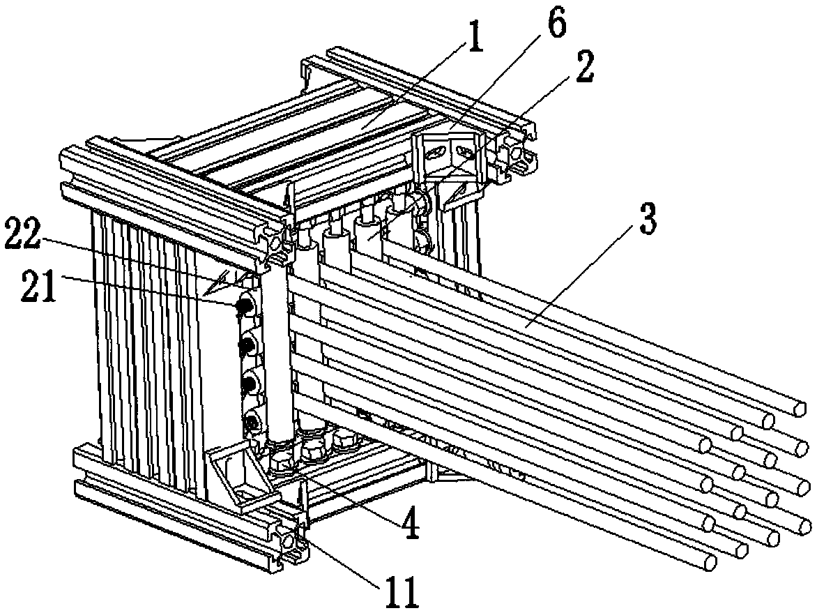
[0014] Such as Figure 1-2 As shown, a cable splitter includes an outer frame 1 and several roller groups installed on the outer frame 1, each roller group includes several parallel and spaced rollers 2, and several roller groups are vertically and horizontally Arranged in a staggered manner, wherein any adjacent two vertically arranged rollers and any adjacent two horizontal rollers form a three-dimensional "well" structure, and the cables 3 can pass through...


PUM


Abstract

The invention discloses a cable deconcentrator, including an outer frame and a plurality of roller sets mounted on the outer frame. Each roller set includes a plurality of rollers parallelly arrangedat intervals, the plurality of roller sets are arranged in a criss-cross manner, arbitrary two adjacent rollers which are longitudinally arranged and arbitrary two adjacent rollers in a transverse direction form a #-shaped structure in a three-dimensional space, and a cable is arranged in the mouth of the #-shaped structure in a penetrating manner. Cable isolation adopts a criss-cross roller design, assembling can be performed according to the requirements of the number and size of cables, due to a stereoscopic deconcentrating structure, the cable can be deconcentrated in an ordered manner, the sequence of the cables does not need to be identified by a tester one by one, false wiring is avoided, stress of connecting devices due to weight of the cables themselves is reduced, and the servicelives of the expensive cables are prolonged.

Description

technical field [0001] The invention relates to the technical field of radar engineering, in particular to a cable splitter. Background technique [0002] In order to improve the test efficiency, the high and low temperature tests of the RF transceiver components of the active phased array radar are carried out at the same time. The RF connection before the test is complicated, and each test requires the tester to identify their line sequence one by one. , It takes a lot of time, and the number of tests will cause the cables to be messy. If there is a slight negligence, the connection may be wrong. The wrong connection will make the test results inconsistent with the actual data of the RF transceiver components, thus assembling on the radar will reduce the performance of the radar system. . Contents of the invention [0003] Based on the deficiencies of the prior art, the purpose of the present invention is to provide a cable splitter, which is used to adjust the splittin...

Claims


Application Information

Patent Timeline
Patent Type & Authority Applications(China)
IPC IPC(8): H02G3/08H01R43/28
CPCH01R43/28H02G3/08
Inventor 包晓军李琳王育才刘远曦刘宏宗刘卫峰
Owner XTR SOLUTIONS
Learn More