
Novel power grid wiring apparatus

A wiring device and power grid technology, applied in the direction of overhead lines/cable equipment, etc., can solve the problems of large number of cables, low efficiency of workers' wiring work, and a large number of other problems

Active Publication Date: 2018-05-18
重庆三创电力工程有限公司
View PDF6 Cites 0 Cited by
  • Summary
  • Abstract
  • Description
  • Claims
  • Application Information

AI Technical Summary

Problems solved by technology

[0002] With the rapid development of my country's modern power technology, the development of power equipment is getting faster and faster. The laying of many cables requires a lot of manpower and material resources. In addition, the current society's demand for electricity is gradually increasing, and the number of utility poles is increasing. The number of cables installed and repaired is extremely large, and the work efficiency of workers in wiring is not high
[0003] At present, the cable wiring work is done by workers purely by hand. The workers lay the wires on the ground, and then the workers climb to the top of the utility poles through the ladders to fix the cables on the utility poles. It is not only wasteful for the workers to lay the cables on the ground. It takes a lot of time, and the process of subsequent workers climbing the ladder is extremely dangerous, which not only has low work efficiency and high risk factor, but also requires a lot of manpower and material resources

Method used


Image

  • Novel power grid wiring apparatus
  • Novel power grid wiring apparatus
  • Novel power grid wiring apparatus

Examples


Embodiment Construction

[0018] The present invention is realized through the following technical solutions:

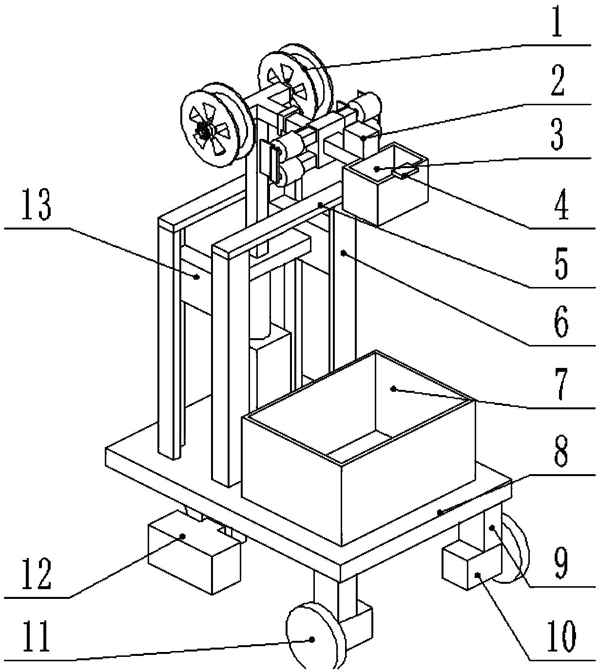
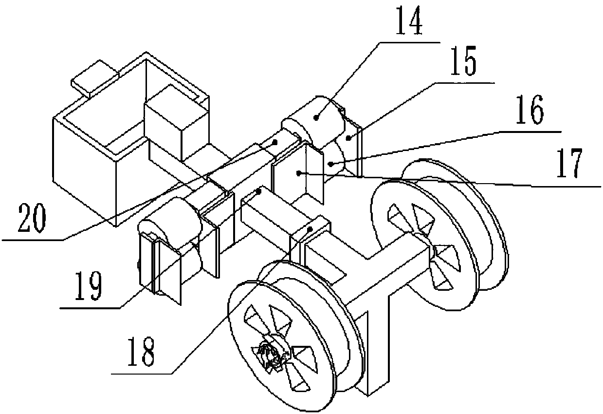
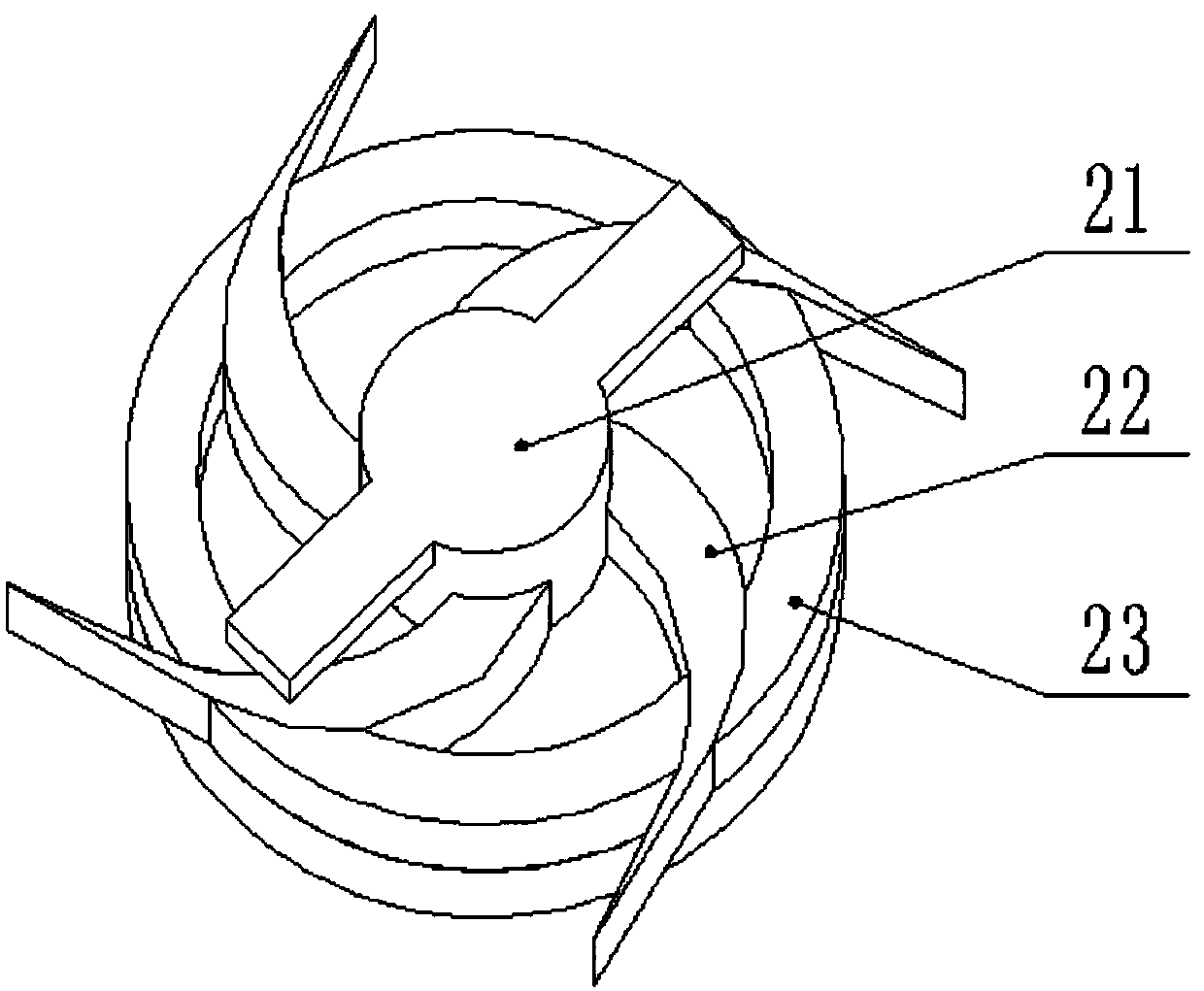
[0019] A new type of power grid wiring device, including wire wheel 1, controller 2, workbench 3, control panel 4, limit baffle 5, first bracket 6, wire storage box 7, chassis 8, first motor 10 base 9 , the first motor 10, the wheel 11, the counterweight 12, the slider 13, the upper pressing wheel 14, the first baffle 15, the upper pressing wheel 16, the second baffle 17, the pressure sensor 18, the second support 19, Second motor 20, knob 21, rubber baffle plate 22, guide wheel 23, counterweight support 24, universal wheel 25, the 3rd support 26 and hydraulic cylinder 27, described wire wheel 1 is installed on the second support 19, it Positions are located on both sides of the second support 19, and the number is two. The controller 2 is installed above the second support 19, the workbench 3 is installed at one end of the second support 19, and the control panel 4 is installed on the workbe...


PUM


Abstract

The invention discloses a novel power grid wiring apparatus, and belongs to the field of electric power equipment. Wire wheels are mounted on a second bracket; a working table is mounted at one end ofthe second bracket; a weight balancing part is mounted below a base; a first wire pressing wheel is positioned above a second wire pressing wheel; the second wire pressing wheel is positioned below the first wire pressing wheel; a pressure sensor is mounted between the second bracket and a third bracket; a hydraulic cylinder is connected with the third bracket; by virtue of the pressure sensor, the pulling force is detected, and a pulling force signal is transmitted to a controller, so that the controller controls the second electric motors to rotate, and rotation of the second electric motors drives the upper wire pressing wheel and the lower wire pressing wheel to rotate so as to drive a cable to move, thereby controlling laying of the cable and ensuring the laying quality of the cable;and a worker controls a control panel on the working table in the high altitude to replace a condition that the worker stands on the top of a telegraph pole for a long time, so that wiring working efficiency is improved and safety in the wiring process is ensured.

Description

technical field [0001] The invention designs a new type of power grid wiring device, specifically a device that realizes cable wiring through the rotation of a wire wheel and the detection of a pressure sensor in conjunction with the work of an upper crimping wheel and a lower crimping wheel, and belongs to the field of electric equipment. Background technique [0002] With the rapid development of my country's modern power technology, the development of power equipment is getting faster and faster. The laying of many cables requires a lot of manpower and material resources. In addition, the current society's demand for electricity is gradually increasing, and the number of utility poles is increasing. The number of cables installed and overhauled is extremely large, and the work efficiency of workers wiring is not high. [0003] At present, the cable wiring work is done by workers purely by hand. The workers lay the wires on the ground, and then the workers climb to the top ...

Claims


Application Information

Patent Timeline
IPC IPC(8): H02G1/04
CPCH02G1/04
Inventor 李习勇
Owner 重庆三创电力工程有限公司
Learn More