
Turnover type unconsolidated sediment sampling device

A sampling device and sediment technology, applied in the direction of sampling devices, sampling, measuring devices, etc., can solve the problems of large sample disturbance, sampling depth limitation, sample loss, etc., to improve the accuracy of the back cover, reduce the difficulty of installation, and improve the installation efficiency Effect

Pending Publication Date: 2018-05-18
CHINA UNIV OF PETROLEUM (EAST CHINA)
View PDF0 Cites 8 Cited by
  • Summary
  • Abstract
  • Description
  • Claims
  • Application Information

AI Technical Summary

Problems solved by technology

At present, sediment samplers are mainly divided into two types: grab type and column type. The grab type sampler has a simple structure, but it has a large disturbance to the sample, the sampling depth is limited, and there is a problem of sample loss due to low airtightness. Used to collect surface samples of sediment; columnar samplers are used to obtain sediment samples by inserting vertically into the sediment
Generally, the columnar sampler has a complex structure and a large volume, and requires an external power supply and is relatively expensive; some columnar samplers with simple structures usually lack an effective sediment sealing device at the bottom of the sampling tube, so that loose sediment is pulled out when the sampler is pulled out. At the same time, the sampling cylinder of the traditional sampler cannot be disassembled, which inevitably destroys the shape of the sample when it is taken out of the sampling cylinder, and it is difficult to obtain a relatively complete columnar sample.

Method used


Image

  • Turnover type unconsolidated sediment sampling device
  • Turnover type unconsolidated sediment sampling device
  • Turnover type unconsolidated sediment sampling device

Examples


Embodiment Construction

[0035] The following will clearly and completely describe the technical solutions in the embodiments of the present invention with reference to the accompanying drawings in the embodiments of the present invention. Obviously, the described embodiments are only some, not all, embodiments of the present invention. Based on the embodiments of the present invention, all other embodiments obtained by persons of ordinary skill in the art without making creative efforts belong to the protection scope of the present invention.

[0036] The terms "first", "second", and the like in the description and claims of the present invention and the above drawings are used to distinguish similar objects, and are not necessarily used to describe a specific sequence or sequence. It is to be understood that the data so used are interchangeable under appropriate circumstances such that the embodiments of the invention described herein are, for example, capable of practice in sequences other than thos...


PUM


Abstract

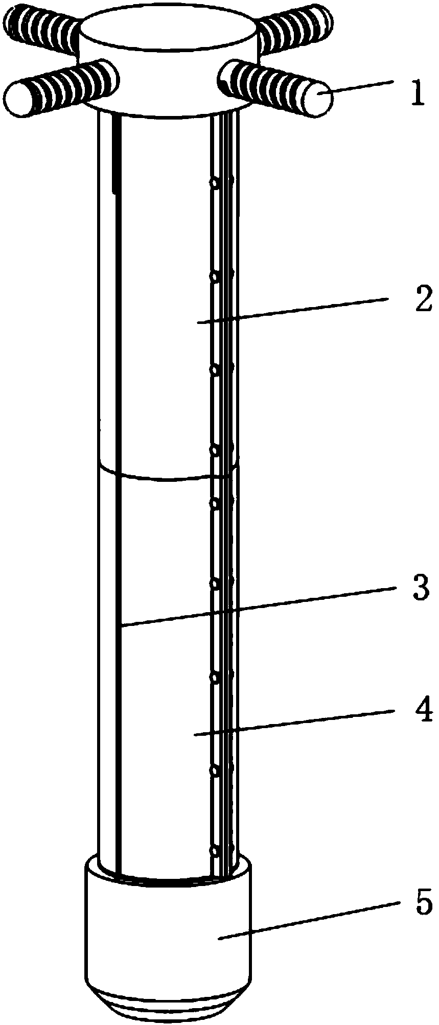
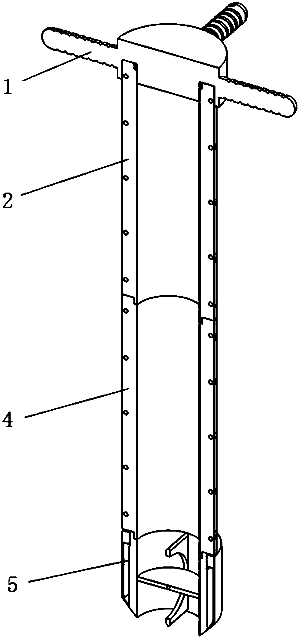
The invention relates to a sampling device and in particular to a turnover type unconsolidated sediment sampling device which comprises a sampling end cover, a first sampling cylinder, a steel wire rope, a second sampling cylinder and a sampler, wherein the lower end of the sampling end cover is mounted at the upper end of the first sampling cylinder; the lower end of the first sampling cylinder is in threaded connection with the upper end of the second sampling cylinder; the lower end of the second sampling cylinder is in threaded connection with the upper end of the sampler; the upper end ofthe steel wire rope is connected with the sampling end cover; the lower end of the steel wire rope is connected with the sampler. The sampling device has the beneficial effects of being simple in structure and convenient to operate, requirements of different sampling depths can be met by increasing and decreasing the number of the second sampling cylinders according to sampling depths, the sampling cylinder can be divided into two parts, morphology of a sample is not damaged when being taken out from the sampling cylinder, and thus a relatively complete columnar sample can be taken; when sediment is pulled out, the bottom of the sampling device can be tightly sealed, so that loss of an unconsolidated sediment sample is effectively prevented, and original properties of a taken sample can be relatively well maintained.

Description

technical field [0001] The invention relates to a sampling device, in particular to a flip-type loose sediment sampling device. Background technique [0002] Loose sediments such as sand and mud are of great significance for revealing environmental changes, depositional processes, and pollutant migration. The sampling often requires keeping the original sequence and sedimentary thickness of the sediments as well as possible. At present, sediment samplers are mainly divided into two types: grab type and column type. The grab type sampler has a simple structure, but it has a large disturbance to the sample, the sampling depth is limited, and there is a problem of sample loss due to low airtightness. Used to collect surface samples of sediment; columnar samplers are used to obtain sediment samples by inserting vertically into the sediment. Generally, the columnar sampler has a complex structure and a large volume, and requires an external power supply and is relatively expensi...

Claims


Application Information

Patent Timeline
IPC IPC(8): G01N1/10
CPCG01N1/10G01N2001/1025
Inventor 邱隆伟杜双虎孙锂徐文豪汤丽莉
Owner CHINA UNIV OF PETROLEUM (EAST CHINA)
Learn More