


Quick Research
Generate reliable direction feasibility study reports for your R&D in just a few steps.

Technical Q&A
Discover and master advanced knowledge NOW. Basics, ideas, possibilities, all at once.

Find Solutions
As an expert in R&D theories, this can generate solutions to your technical problems instantly.

Evaluate Feasibility
Analyze your overall solution with one click, know your potential R&D risks in advance.

Monitor Landscape
Get weekly tech updates, stay abreast of the latest tech innovations and key insights.
Cross-beam-free type dispersing deflexion expansion joint mechanism
A technology of expansion joints and displacement, which is applied in the direction of bridges, bridge parts, bridge construction, etc., can solve the problems of frequent expansion joint diseases, single function reduction, and complex structure, so as to achieve reliable longitudinal expansion function, simplified structure, and easy maintenance. good replacement condition
- Summary
- Abstract
- Description
- Claims
- Application Information
AI Technical Summary
Problems solved by technology
Method used
Image


Examples
Embodiment 1
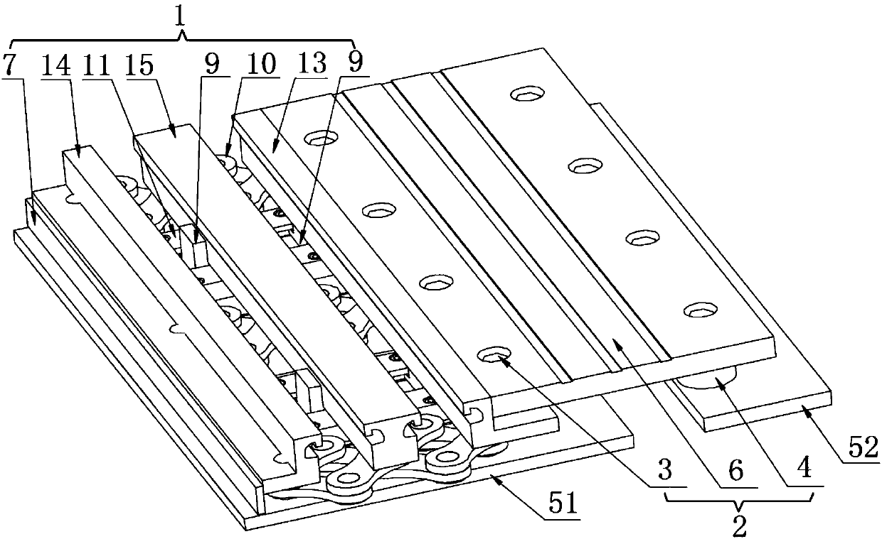
[0024] like figure 1 , 2 As shown, a cross-beam-free distributed displacement expansion joint mechanism includes a displacement assembly 1 and a spanning assembly 2. The displacement assembly 1 includes a first side beam 13, a second side beam 14, a middle beam 15, and a connecting rod assembly 10. Guide rail assembly 11, center beam slider 8, side beam slider 9 and sealing plate 7; the first side beam 13 and the second side beam 14 are respectively placed on both sides of the center beam 15; the cross-joint assembly 2 includes an outer hexagon Bolt 3, elastic support 4 and seam-spanning plate 6; displacement assembly 1 is located on the first bottom plate 51, first side beam 13, second side beam 14 and middle beam 15 are respectively intermittently arranged in the direction of the lower cross bridge. , guide rail assembly 11, side beam slider 9 and center beam slider 8; the seam-spanning assembly 2 is respectively fixed on the first side beam 13 and the second bottom plate 5...
Embodiment 2
[0029] A cross-beam-free distributed displacement expansion joint mechanism, including a displacement assembly 1 and a joint-spanning assembly 2, the displacement assembly 1 includes a first side beam 13, a second side beam 14, a middle beam 15, a connecting rod assembly 10, and a guide rail Assembly 11, middle beam slider 8, side beam slider 9 and sealing plate 7; the first side beam 13 and the second side beam 14 are respectively placed on both sides of the middle beam 15; The elastic support 4 and the seam-spanning plate 6; the displacement assembly 1 is located on the first bottom plate 51, and the first side beam 13, the second side beam 14, and the middle beam 15 are respectively intermittently arranged in the direction of the lower cross bridge. 11. The side beam slider 9 and the middle beam slider 8; the seam-spanning assembly 2 is respectively fixed on the first side beam 13 and the second bottom plate 52 through the outer hexagonal bolt 3 and the elastic support 4 . ...
Embodiment 3
[0036] A cross-beam-free distributed displacement expansion joint mechanism, including a displacement assembly 1 and a joint-spanning assembly 2, the displacement assembly 1 includes a first side beam 13, a second side beam 14, a middle beam 15, a connecting rod assembly 10, and a guide rail Assembly 11, middle beam slider 8, side beam slider 9 and sealing plate 7; the first side beam 13 and the second side beam 14 are respectively placed on both sides of the middle beam 15; The elastic support 4 and the seam-spanning plate 6; the displacement assembly 1 is located on the first bottom plate 51, and the first side beam 13, the second side beam 14, and the middle beam 15 are respectively intermittently arranged in the direction of the lower cross bridge. 11. The side beam slider 9 and the middle beam slider 8; the seam-spanning assembly 2 is respectively fixed on the first side beam 13 and the second bottom plate 52 through the outer hexagonal bolt 3 and the elastic support 4 . ...
PUM
 Abstract
Description
Claims
Application Information
 - R&D Engineer
- R&D Manager
- IP Professional
- Industry Leading Data Capabilities
- Powerful AI technology
- Patent DNA Extraction
Browse by: Latest US Patents, China's latest patents, Technical Efficacy Thesaurus, Application Domain, Technology Topic, Popular Technical Reports.
© 2024 PatSnap. All rights reserved.Legal|Privacy policy|Modern Slavery Act Transparency Statement|Sitemap|About US| Contact US: help@patsnap.com