
Lifting type floating feeding device

A lifting type, lifting drive mechanism technology, applied in auxiliary devices, auxiliary welding equipment, welding/cutting auxiliary equipment, etc., can solve the problem that the positioner cannot realize the automatic clamping of the workpiece, the positioning accuracy of the clamping is poor, and the labor intensity is high And other problems, to achieve the effect of improving the working accuracy and service life, stable and reliable work, simple and compact structure

Active Publication Date: 2018-05-18
ZHUZHOU TIANYI AUTOWELDING SYST CO LTD
View PDF6 Cites 0 Cited by
  • Summary
  • Abstract
  • Description
  • Claims
  • Application Information

AI Technical Summary

Problems solved by technology

The existing positioner cannot realize the automatic clamping of the workpiece, and manual operation is required to complete the clamping of the workpiece, which has the problems of high labor intensity, low efficiency, poor safety, and poor clamping and positioning accuracy

Method used


Image

  • Lifting type floating feeding device
  • Lifting type floating feeding device
  • Lifting type floating feeding device

Examples


Embodiment Construction

[0018] The present invention will be described in further detail below in conjunction with the accompanying drawings and specific embodiments.

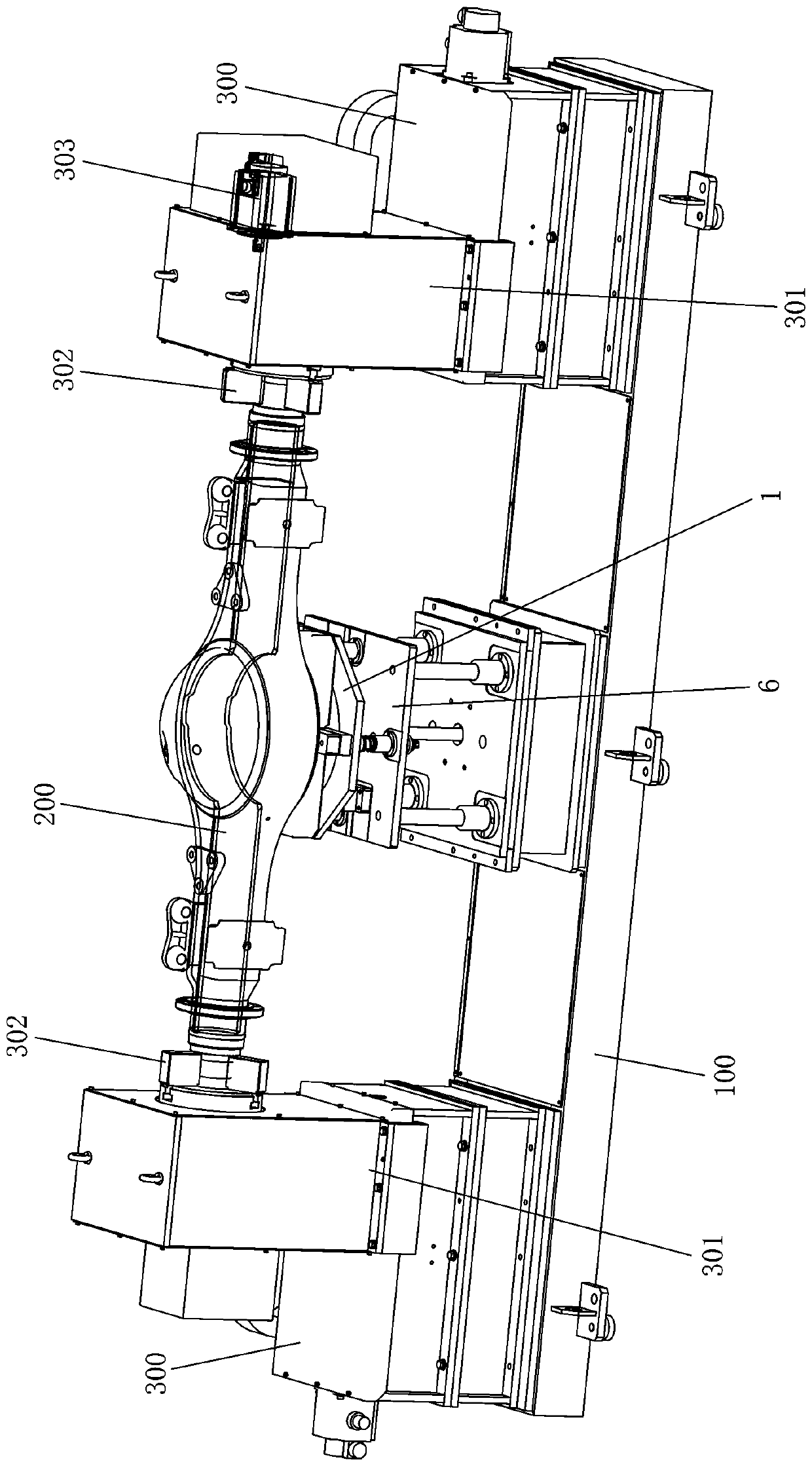
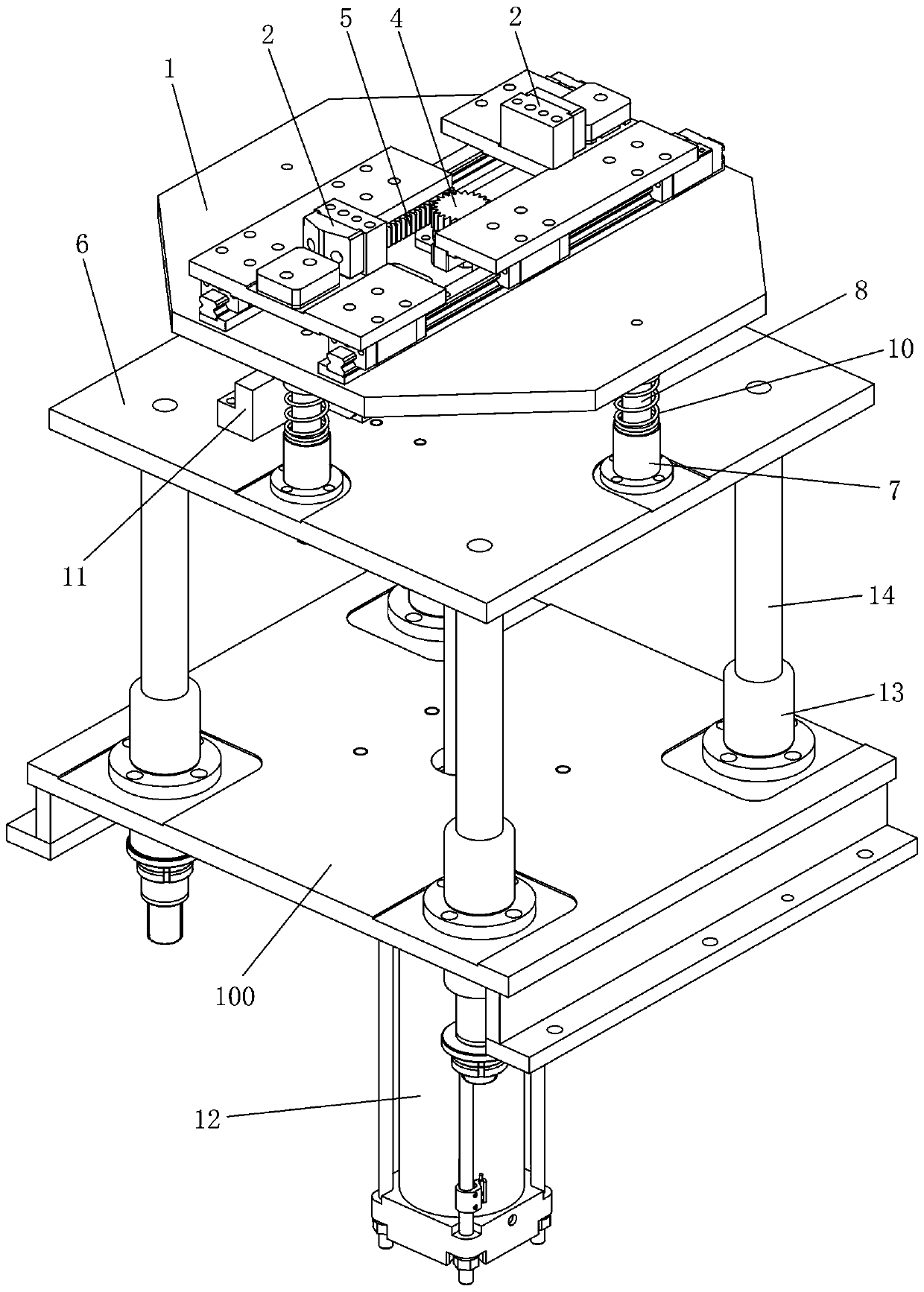
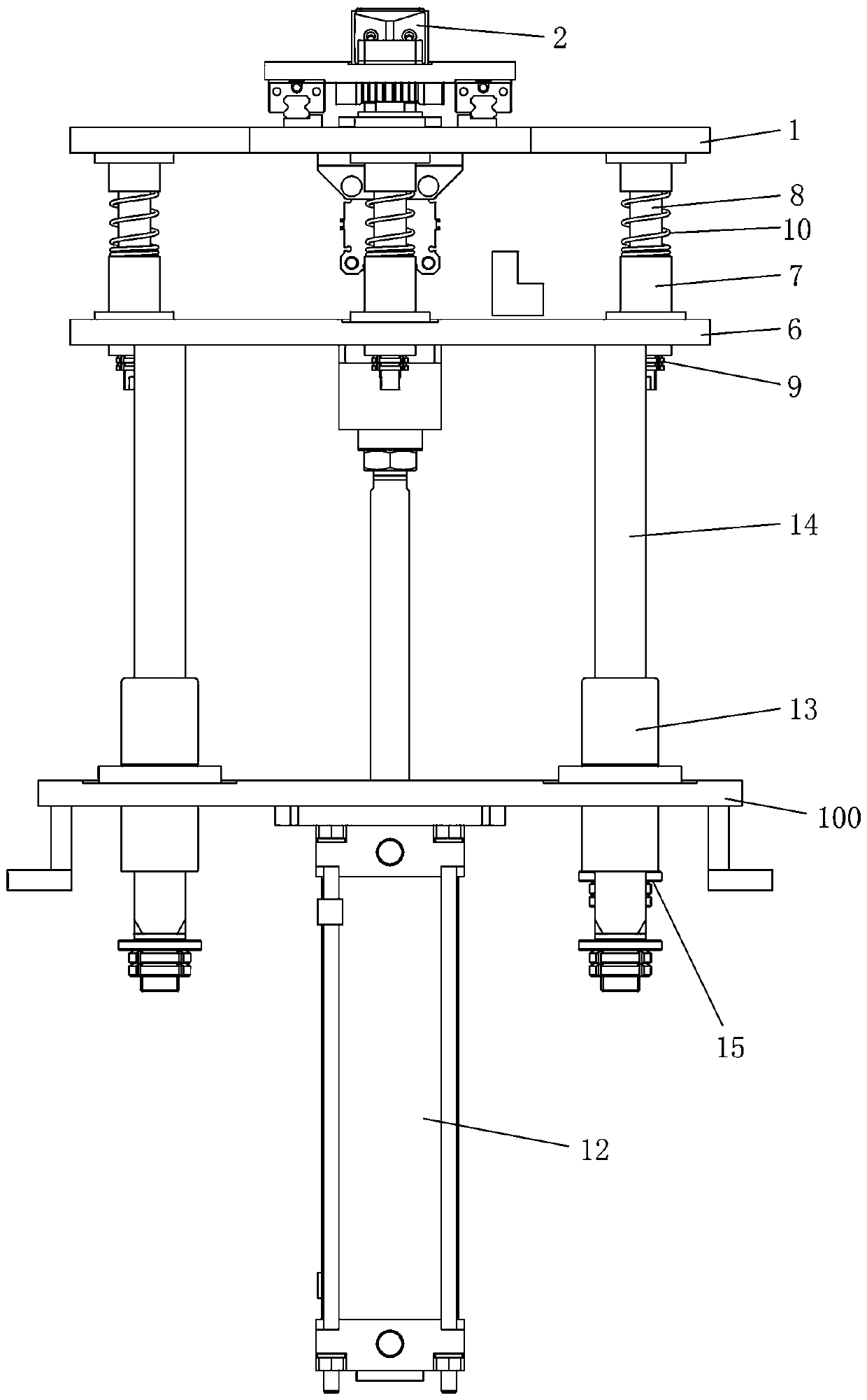
[0019] like Figure 2 to Figure 4 As shown, the lift-type floating feeding device of this embodiment includes a frame 100, a holding base 1 and a fixing assembly arranged on the holding base 1 for fixing the workpiece 200, and the holding base 1 is installed on the machine through the lifting assembly. On the frame 100, the lifting assembly includes the lifting seat 6 which is slid on the frame 100 in the vertical direction and the lifting drive mechanism for driving the lifting seat 6 to move up and down on the mounting frame 100, and the supporting seat 1 is installed on the frame by a floating mechanism. Lifting seat 6 and can elastically float up and down on lifting seat 6. The lift-type floating feeding device uses a fixed component to fix the workpiece 200, and the lifting component drives the supporting seat 1 to move up and d...


PUM


Abstract

The invention discloses a lifting type floating feeding device comprising a machine frame, a holding seat and a fixing assembly which is arranged on the holding seat and used for fixing a workpiece. The holding seat is installed on the machine frame through a lifting assembly. The lifting assembly comprises a lifting seat arranged on the machine frame in the vertical direction in a sliding mannerand a lifting drive mechanism installed on the machine frame and used for driving the lifting seat to ascend and descend. The holding seat is installed on the lifting seat through a floating mechanismand can elastically float up and down on the lifting seat. The lifting type floating feeding device has the advantages of being simple and compact in structure, low in cost, stable and reliable in work, easy to control, long in service life, good in flexibility and the like.

Description

technical field [0001] The invention relates to the technical field of industrial robots, in particular to a lifting floating feeding device. Background technique [0002] The positioner can be used to clamp the workpiece for welding and other operations on the workpiece. The existing positioner cannot realize the automatic clamping of the workpiece, and manual operation is required to complete the clamping of the workpiece, which has the problems of high labor intensity, low efficiency, poor safety, and poor clamping and positioning accuracy. Contents of the invention [0003] The technical problem to be solved by the present invention is to overcome the deficiencies of the prior art and provide a lifting floating feeding device with simple and compact structure, low cost, stable and reliable operation, easy control, long service life and good flexibility. [0004] In order to solve the problems of the technologies described above, the present invention adopts the follow...

Claims


Application Information

Patent Timeline
IPC IPC(8): B23K37/00B23K37/04B23K37/047
CPCB23K37/00B23K37/0443B23K37/047
Inventor 胡渊俊谭永胜徐敏袁斌
Owner ZHUZHOU TIANYI AUTOWELDING SYST CO LTD
Learn More