
A fog-through TV system based on continuous zoom lens

A technology of zoom lens and TV system, which is applied in the parts of TV system, TV, color TV, etc., can solve the problems of inability to fully satisfy ultra-long-distance imaging and observation, unsuitable for portable use, poor image processing ability, etc. Improved portability and operability, continuous auto zoom, improved quality and precision

Active Publication Date: 2020-10-02
HUBEI HUAZHONG PHOTOELECTRIC SCI & TECH
View PDF8 Cites 0 Cited by
  • Summary
  • Abstract
  • Description
  • Claims
  • Application Information

AI Technical Summary

Problems solved by technology

[0003] In the prior art, fog penetration imaging usually uses infrared imaging or near-infrared television imaging. Although this can achieve fog penetration imaging of the picture to be collected to a certain extent, due to the resolution of the infrared imaging core detector (usually 640×512) is relatively low, and the pixel size (usually 17 μm) is relatively large, resulting in a large volume of the entire imaging system, which is not suitable for portable use, and cannot fully meet the needs of ultra-long-distance imaging and observation; Although the resolution of near-infrared television imaging has been improved to a certain extent and the pixel size has also been reduced to a certain extent, the existing near-infrared television imaging has poor image processing capabilities and cannot effectively adapt to the clear image of complex environments. Imaging shooting, its application has great limitations, and there is a problem of poor consistency of the optical axis in the process of continuous shooting and field of view conversion, and the imaging quality is greatly affected

Method used


Image

  • A fog-through TV system based on continuous zoom lens
  • A fog-through TV system based on continuous zoom lens
  • A fog-through TV system based on continuous zoom lens

Examples


Embodiment Construction

[0036] In order to make the object, technical solution and advantages of the present invention clearer, the present invention will be further described in detail below in conjunction with the accompanying drawings and embodiments. It should be understood that the specific embodiments described here are only used to explain the present invention, not to limit the present invention.

[0037] In addition, the technical features involved in the various embodiments of the present invention described below can be combined with each other as long as they do not constitute a conflict with each other.

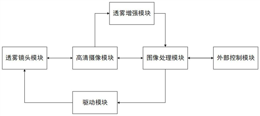
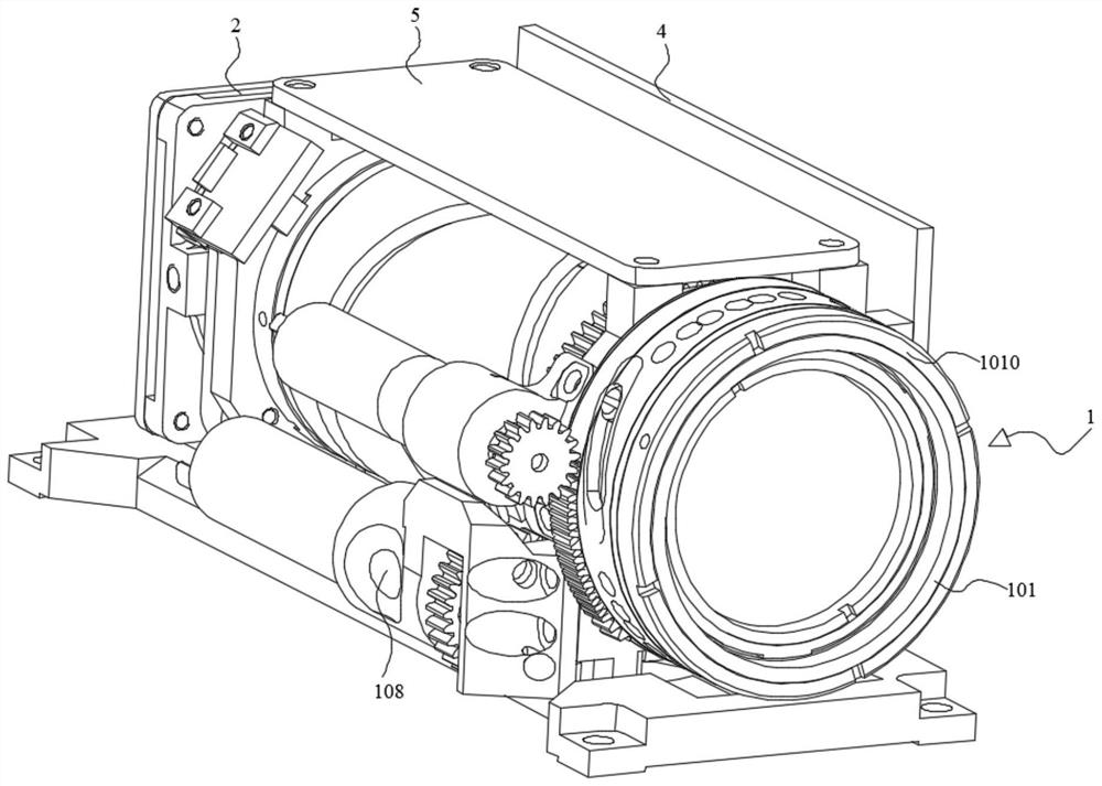
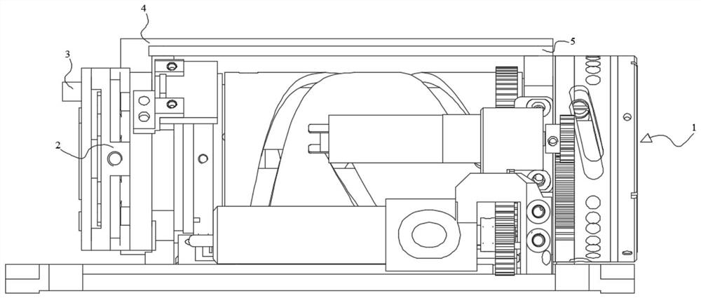
[0038] The present invention is based on the fog-penetrating TV system of the continuous zoom lens, and its system schematic diagram is as follows figure 1 As shown in , it mainly includes a fog penetration lens module 1, a high-definition camera module 2, a fog penetration enhancement module 3, an image processing module 4 and a drive module 5, and the above modules are assembled into ...


PUM


Abstract

The invention discloses a fog-penetrating TV system based on a continuous zoom lens, which belongs to the related technical field of photoelectric technology. It works by setting a fog-penetrating lens module, a high-definition camera module, a fog-penetrating enhancement module, a driving module and an image processing module for matching and connection work. Under the control of the image processing module, the driving module drives the fog penetration lens module to continuously zoom to image the captured picture. After receiving the instructions from the image processing module, the high-definition camera module captures the captured picture and sends it to the fog penetration enhancement module for clearing. The fog penetration enhancement module sends the processed captured picture to the image processing module, which encodes the captured picture and sends it out to complete the picture image capture. The fog-penetrating TV system based on the continuous zoom lens of the present invention has a simple and portable structure, and is easy to operate and control. It not only ensures the accuracy and efficiency of image acquisition of the fog-penetrating TV system, but also greatly improves the environmental applicability and compatibility of the fog-penetrating TV system. sex.

Description

technical field [0001] The invention belongs to the related technical field of optoelectronic technology, and in particular relates to a fog-penetrating TV system based on a continuous zoom lens. Background technique [0002] With the continuous development of TV imaging technology, it has been widely used in TV guidance, photoelectric reconnaissance and other technical fields. In the process of TV imaging, continuous zoom lens plays a very important role. Large and small targets are clearly imaged. When the target needs to be searched or observed, the short-focus large field of view is generally used, and when the target needs to be observed and tracked in detail, the long-focus small field of view is generally used, but in the process of field of view conversion , in order to prevent the observed target from disappearing, it is necessary to put forward high requirements on the consistency of the optical axis of the lens. [0003] In the prior art, fog penetration imaging ...

Claims


Application Information

Patent Timeline
Patent Type & Authority Patents(China)
IPC IPC(8): H04N5/225H04N5/232
CPCH04N23/50H04N23/54H04N23/55H04N23/67
Inventor 安伟光侯志超黄德军韩志刚许志波夏苗司永威
Owner HUBEI HUAZHONG PHOTOELECTRIC SCI & TECH
Learn More