
Automatic conveying device of plates

A technology of automatic transmission and sheet metal, applied in the direction of transportation and packaging, conveyors, conveyor objects, etc., can solve the problems of high labor intensity, labor, position movement, etc., and achieve the effect of improving work efficiency and reducing manpower output.

Inactive Publication Date: 2018-05-15
ZHEJIANG UNIV OF TECH FENGHUA SMART ECONOMY RES INST
View PDF6 Cites 5 Cited by
  • Summary
  • Abstract
  • Description
  • Claims
  • Application Information

AI Technical Summary

Problems solved by technology

However, in the field of wood processing, it is often necessary to transport materials such as wood-based panels or plate-shaped raw materials. These materials are square in shape, large in area, and high in quality. It is impossible to accurately and stably complete the transfer of materials,
[0003] The traditional plate transmission requires a lot of labor, and the operation is labor-intensive. It needs to be manually pushed to move the position during the transportation. When aligning the layers of the plate, it is difficult to move laterally, and when the aligned plate is transported on the unpowered roller , easy to generate vibration, causing friction between plates, easy to produce position shift, resulting in inaccurate control dimensions
[0004] The size of the products conveyed by the conveying device used in the prior art is mostly fixed, and the conveying width cannot be adjusted. In this way, plates of different sizes cannot be conveyed, and the versatility of the conveying device cannot be realized.

Method used


Image

  • Automatic conveying device of plates
  • Automatic conveying device of plates
  • Automatic conveying device of plates

Examples


Embodiment Construction

[0033] Below in conjunction with accompanying drawing and embodiment of description, specific embodiment of the present invention is described in further detail:

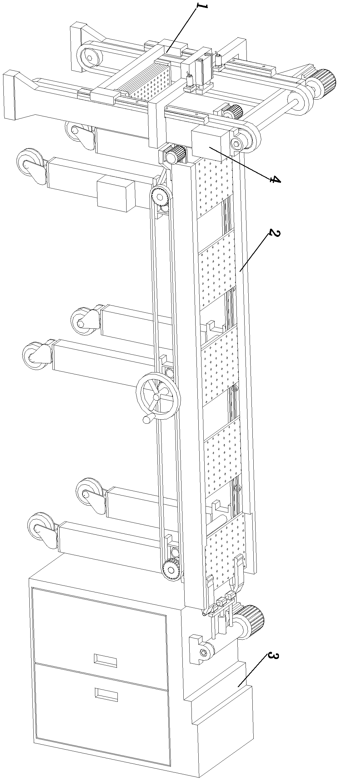
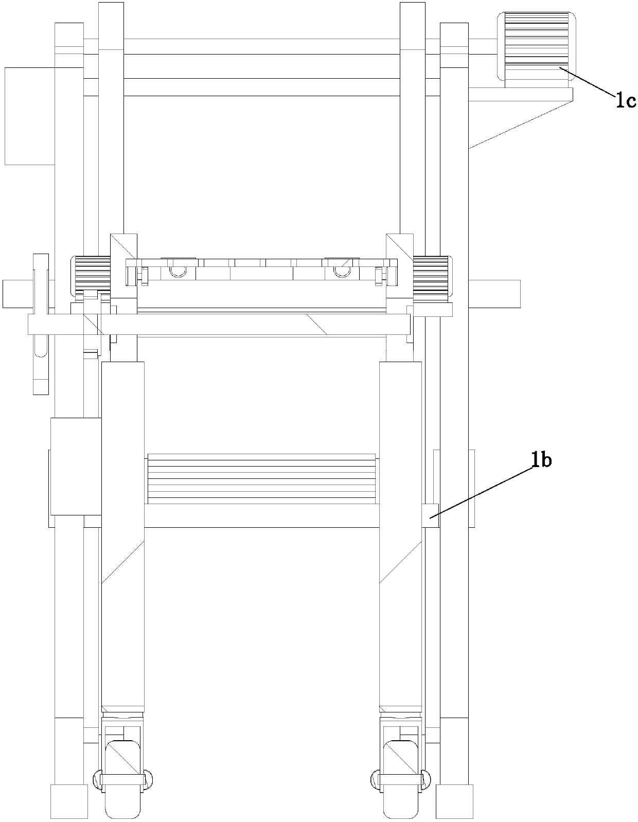
[0034] refer to Figure 1 to Figure 14The shown automatic feeding machine for plates includes a plate feeding mechanism 1, a plate conveying mechanism 2, a plate turning mechanism 3 and a control mechanism 4, and the plate feeding mechanism 1 is arranged at the input end of the plate conveying mechanism 2 , the plate turnover mechanism 3 is arranged at the output end of the plate conveying mechanism 2, and the plate feeding mechanism 1 includes a first mounting frame 1a, a plate material bearing part 1b installed on the first mounting frame 1a, and is used for driving The sheet material receiving part 1b is the first driving part 1c that reciprocates up and down on the first mounting frame 1a and the sheet material pushing that is used to push the sheet to be loaded on the sheet material receiving part 1b to the inp...


PUM


Abstract

The invention relates to the technical field of machining equipment, in particular to an automatic conveying device of plates. The automatic conveying device comprises a plate conveying mechanism anda plate turnover mechanism. The plate conveying mechanism comprises two plate conveying components, and a second drive assembly for driving the to-be-conveyed plates to move is arranged in each plateconveying component. The plate turnover mechanism comprises a work cabinet, a plate turnover component and a plate clamping component. Each plate conveying component comprises a first conveying frameand multiple first supporting plates. An adjusting assembly is arranged between each first supporting plate and the corresponding first conveying frame. Each second drive assembly is fixedly mounted on the corresponding first conveying frame. The plate turnover component comprises a plate drive assembly and a clamping and pushing assembly. The end of the clamping and pushing assembly is fixedly mounted on the plate drive assembly and can do reciprocating motion in the conveying direction of the first conveying frames. According to the automatic conveying device, the automatic conveying manneris adopted, manpower output is reduced, and the plate conveying work efficiency is improved.

Description

technical field [0001] The invention relates to the technical field of processing equipment, in particular to an automatic transmission device for plates. Background technique [0002] The material transmission device is a commonly used basic equipment in the field of wood processing. Due to the limitation of the factory site or the utilization rate of the site in the actual production and processing process, the transmission device in the wood processing plant usually needs to bend the transmission line. fold. However, in the field of wood processing, it is often necessary to transport materials such as wood-based panels or plate-shaped raw materials. These materials are square in shape, large in area, and high in quality. It is impossible to accurately and stably complete the transfer of materials, [0003] The traditional plate transmission requires a lot of labor, and the operation is labor-intensive. It needs to be manually pushed to move the position during the trans...

Claims


Application Information

Patent Timeline
IPC IPC(8): B65G47/04B65G15/22B65G47/248
CPCB65G47/04B65G15/22B65G47/248
Inventor 李伟
Owner ZHEJIANG UNIV OF TECH FENGHUA SMART ECONOMY RES INST
Learn More