
Pneumatic tire

A technology for pneumatic tires and tires, which is applied to pneumatic tires, reinforcement layers of pneumatic tires, heavy-duty tires, etc., can solve the problems of deterioration of durability performance, unrelieved compressive stress, etc., to achieve sufficient bending rigidity, suppress dents, and ensure bending. rigid effect

Active Publication Date: 2018-05-11
SUMITOMO RUBBER IND LTD
View PDF17 Cites 6 Cited by
  • Summary
  • Abstract
  • Description
  • Claims
  • Application Information

AI Technical Summary

Problems solved by technology

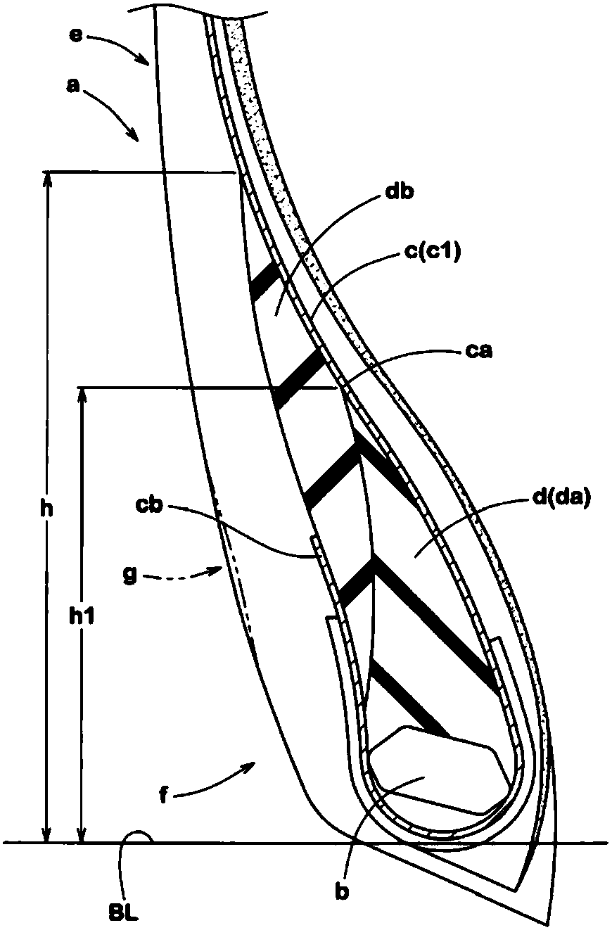
Hence, as in image 3 As indicated by phantom lines, in addition to the formation of the recess g in which the outer surface of the bead portion f is recessed inward in the tire axial direction, there is a problem of deterioration in durability.
In addition, although the strain of the outer end caused by the repeated bending deformation can be suppressed by increasing the rubber hardness of the second rubber portion db, the compressive stress acting on the outer end of the folded portion cb is not relieved, and the durability performance is still maintained. worsening problem

Method used


Image

  • Pneumatic tire
  • Pneumatic tire
  • Pneumatic tire

Examples


Embodiment Construction

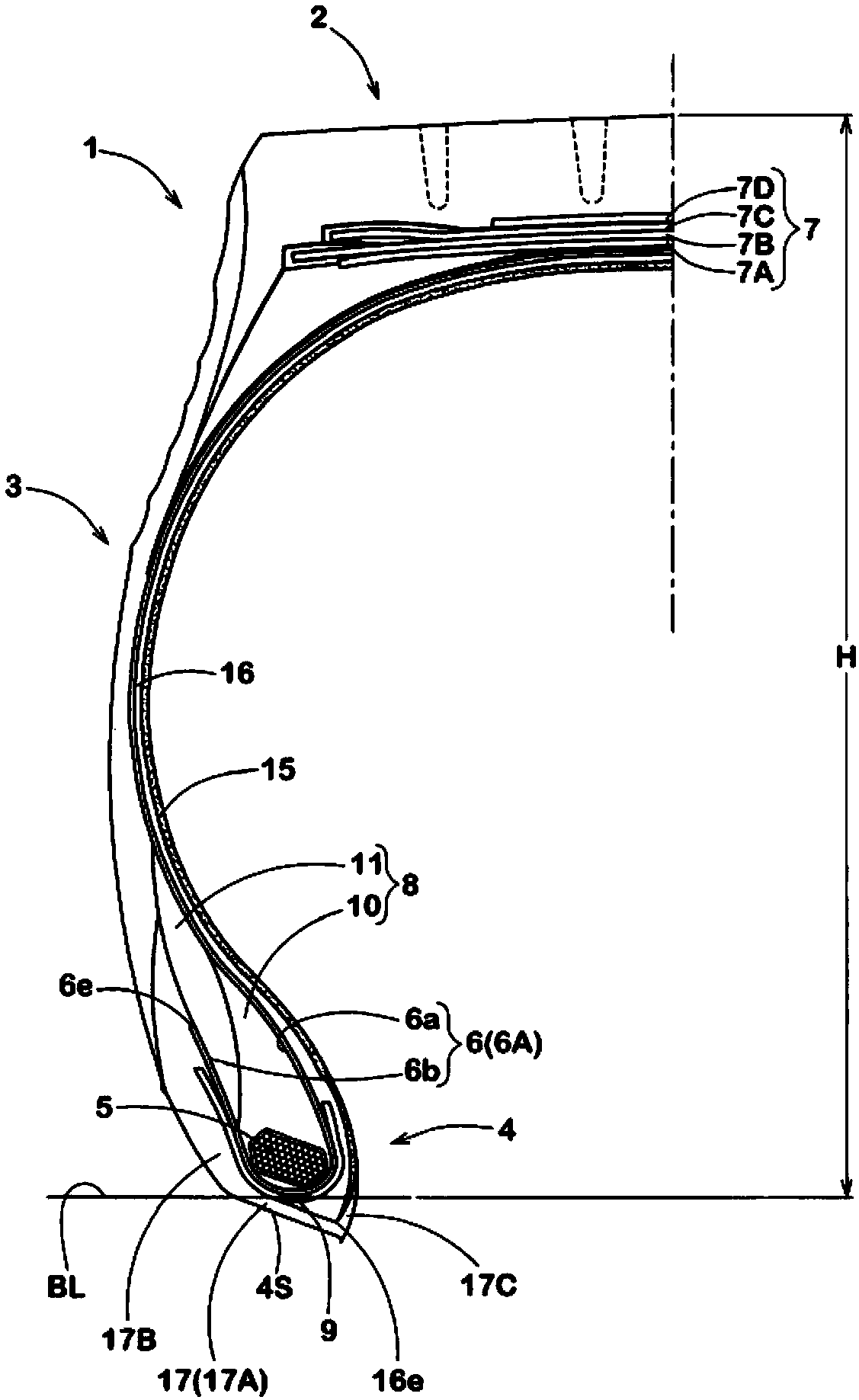
[0017] Hereinafter, one embodiment of the present invention will be described based on the drawings. figure 1 It is a tire meridian cross-sectional view showing a normal state of a pneumatic tire (hereinafter, sometimes simply referred to as a "tire") 1 according to an embodiment of the present invention. The present invention can also be applied to tires for passenger cars, but is particularly suitable for use in tires for heavy loads such as trucks and buses.

[0018] In this specification, "regular state" refers to a state where the tire is assembled on a regular rim (not shown) and filled with a regular internal pressure, and is under no load. Unless otherwise specified, the dimensions of each part of the tire are in the The value measured in this normal state.

[0019] "Regular rims" are rims of different specifications for each tire in the specification system including the specifications on which the tires are based. If it is JATMA, it is "Standard Rim", and if it is ...


PUM


Abstract

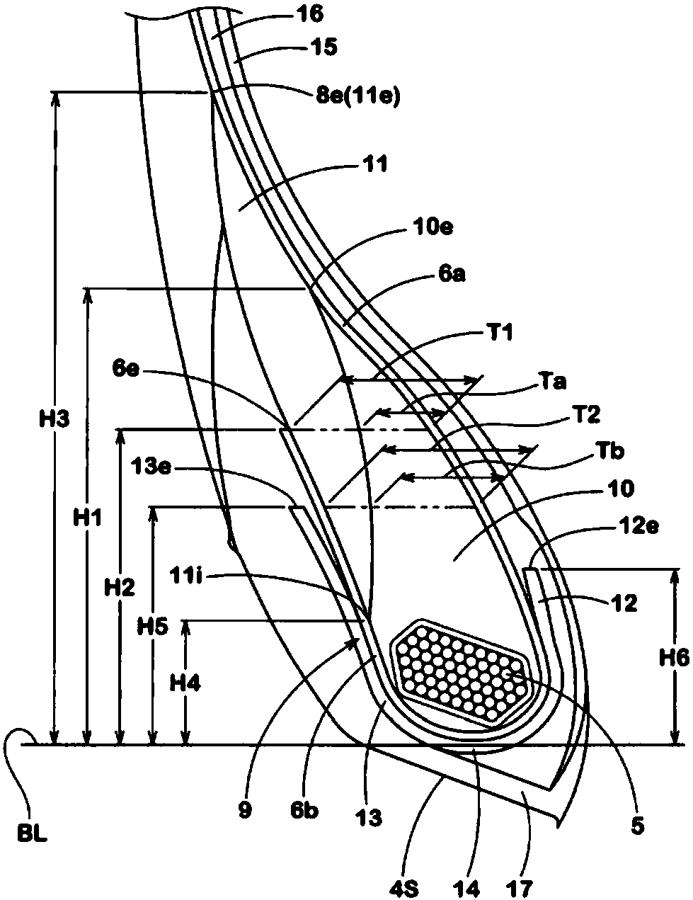
The present invention relates to a pneumatic tire which can improve the endurance performance. The pneumatic tire (1) comprises a carcass (6) comprising a carcass ply (6A) comprising a main body portion (6a) and turned up portions (6b), and bead apex rubbers (8). Each of the bead apex rubbers (8) comprises a first rubber portion (10) and a second rubber portion (11) provided on an outer side in atire axial direction of the first rubber portion and having smaller rubber hardness than the first rubber portion. A ratio H1 / H2 of a height (H1) of an outer end (10e) in a tire radial direction of the first rubber portion (10) from a bead base line (BL) and a height (H2) of an outer end in the tire radial direction of each of the turned up portions (6b) from the bead base line (BL) is in a rangeof from 1.4 to 1.7.

Description

technical field [0001] The present invention relates to a pneumatic tire with improved durability. Background technique [0002] Such as image 3 As shown, there is known a pneumatic tire a including a carcass c composed of carcass plies c1 folded back around a bead core b, and a bead apex d disposed between the folded carcass plies c1. The carcass c includes a main body portion ca that reaches the bead core b of the bead portion f from the tread portion (not shown) via the sidewall portion e, and a turn-back portion cb that turns around the bead core b from the inside to the outside in the tire axial direction. . The bead apex d includes a first rubber portion da and a second rubber portion db arranged on the outer side of the first rubber portion da in the tire axial direction and having a lower rubber hardness than the first rubber portion da. In the above-mentioned pneumatic tire a, for example, the following Patent Document 1 describes that the height h1 of the first ...

Claims


Application Information

Patent Timeline
Patent Type & Authority Applications(China)
IPC IPC(8): B60C9/02B60C15/04
CPCB60C9/02B60C15/04B60C15/0036B60C15/0607B60C15/0635B60C2015/061B60C15/0009B60C15/0653B60C2005/145B60C2015/009B60C2200/06Y10T152/10837
Inventor 佐藤华奈
Owner SUMITOMO RUBBER IND LTD
Learn More