
Database access method and system

An access method and database technology, applied in the direction of database distribution/replication, structured data retrieval, special data processing applications, etc., can solve problems such as accessing wrong databases, network address conflicts, accessing errors, etc., to achieve improved reliability, reliable host Standby switching and little impact on the network

Active Publication Date: 2020-08-04
杭州有赞科技有限公司
View PDF5 Cites 0 Cited by
  • Summary
  • Abstract
  • Description
  • Claims
  • Application Information

AI Technical Summary

Problems solved by technology

If the client fails to receive the broadcast, it cannot perceive the change of the virtual network address, which will lead to access to the wrong database
[0003] Therefore, the existing method of using the virtual network address to realize client access to a changing database is easily affected by the network, and a network address conflict occurs when the virtual network address fails to be uninstalled, or the client fails to receive the address resolution protocol broadcast. Faults causing access errors, poor reliability

Method used


Image

  • Database access method and system
  • Database access method and system
  • Database access method and system

Examples


Embodiment 2

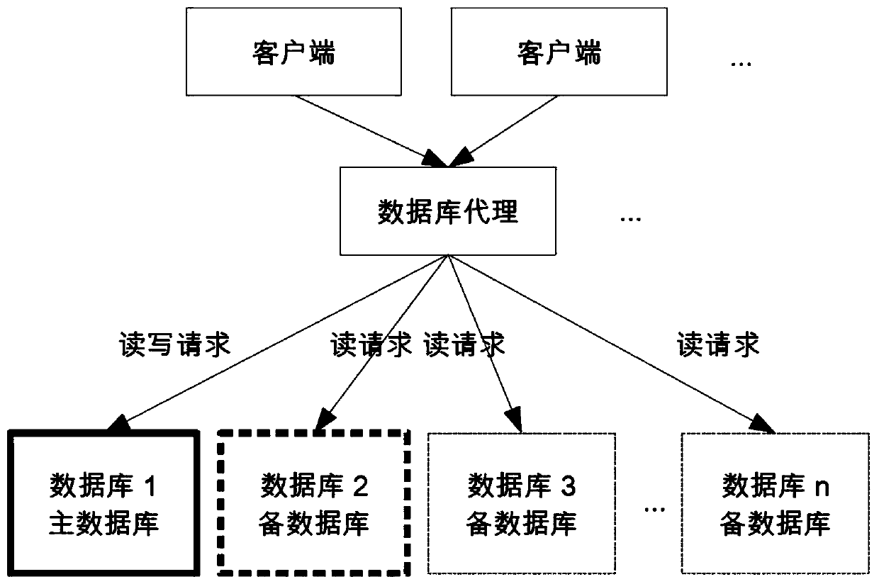
[0079] see image 3 and Figure 4 , Embodiment 2: active switching

[0080] Such as image 3 As shown, the initial state: database 1 is the primary database, which can provide write requests; database 2, database 3 to database n are standby databases, which can only provide read requests, and select database 2 as the new primary database.

[0081] The switching process is as Figure 4 shown, including the following steps:

[0082] S11. Send a request to downgrade the database 1 to the database agent.

[0083] Since there may be one or more database agents, you must wait for all database agents to return a successful result or confirm that the database agent no longer provides services before proceeding to the next step to ensure data consistency. After the S11 operation is completed, the database agent no longer forwards the write request to the database 1.

[0084] S12, database 2 and database 1 perform data synchronization.

[0085] After this step is completed, the d...

Embodiment 3

[0092] see Figure 5 and Figure 6 , Embodiment Three: Failover

[0093] Such as Figure 5 As shown, the initial state: database 1 is the primary database, and has failed; database 2, database 3 to database n are standby databases, which can only provide read requests, and select database 2 as the new primary database.

[0094] The switching process is as Figure 6 shown, including the following steps:

[0095] S21. Send an offline database 1 request to the database agent.

[0096] Since there may be one or more database agents, you must wait for all database agents to return a successful result or confirm that the database agent no longer provides services before proceeding to the next step to ensure data consistency. After the operation is completed, the database agent no longer forwards any requests to database 1, and disconnects the existing connection.

[0097] S22. Synchronize data between database 2 and database n.

[0098] After this step is completed, the data ...


PUM


Abstract

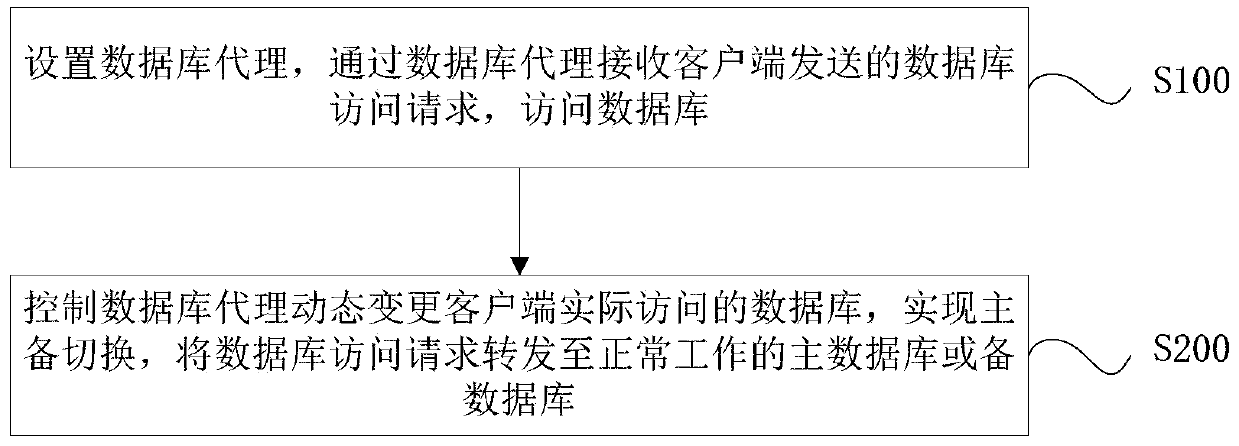
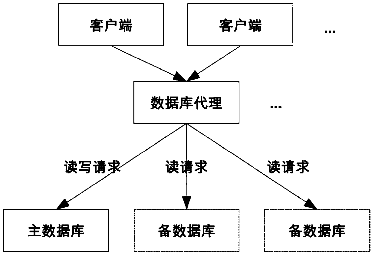
The invention discloses a database visit method and system. The database visit method comprises steps of arranging a database agent, receiving a database visit request sent by a client end via the database agent, visit the database, controlling the database agent to dynamically change a database practically visited by the client end, converting master and spare databases, and transmitting the database visit request to a normally-working master database or a spare database. Master and spare database conversion can be realized when the database practically visited by the client end is dynamically changed by the database agent. Without the use of virtual network addresses, network address conflicts due to failures of unload of the virtual network address, or faults due to failures of reception of address resolution protocols by the client end can be prevented; and database visit reliability can be greatly enhanced.

Description

technical field [0001] The invention relates to the technical field of database systems, in particular to a database access method and system. Background technique [0002] In the prior art, a virtual network address (Virtual IP, VIP for short) is usually used to drift from the primary database to the standby database, so that the client accesses the changed database. When the virtual network address is uninstalled from the server where the main database is located, the uninstallation may not be completed due to host machine failure, which may easily cause network address (ie IP) conflicts. Moreover, when the address of the virtual network changes, an Address Resolution Protocol (ARP) broadcast needs to be sent. If the client fails to receive the broadcast, it cannot perceive the change of the virtual network address, which will lead to access to the wrong database. [0003] Therefore, the existing method of using the virtual network address to realize client access to a c...

Claims


Application Information

Patent Timeline
Patent Type & Authority Patents(China)
IPC IPC(8): G06F16/27
CPCG06F16/27
Inventor 谢振业
Owner 杭州有赞科技有限公司
Learn More