Eureka AIR delivers breakthrough ideas for toughest innovation challenges, trusted by R&D personnel around the world.

Locking device of crane cab

A locking device and cab technology, applied in the directions of transportation and packaging, load hanging components, etc., can solve the problems of complex structure of the hydraulic locker, affecting the balance of the crane, and being difficult to control, and achieve safe and reliable use, convenient operation, and structure. Well-designed effects

Inactive Publication Date: 2018-05-08
德马科起重机械有限公司
View PDF5 Cites 0 Cited by
  • Summary
  • Abstract
  • Description
  • Claims
  • Application Information

AI Technical Summary

Problems solved by technology

[0002] With the needs of economic development and national construction, cranes have developed rapidly in recent years. Due to the actual needs of the project, in order to enable the operators in the cab to have a good vision and avoid unnecessary personal casualties and property losses , most of the crane cabs are designed to be rotatable and pitchable, but the uncontrolled rotation of the turntable will affect the balance of the crane and even cause the crane to roll over when the crane is running. A locking structure is provided for the cab of the crane. In the prior art, there are two common types of locking structures for the crane turntable: a mechanical locker and a hydraulic locker. The structure of the mechanical locker is relatively simple, but it can only lock the turntable at the initial position. , the structure of the hydraulic locker is complex and not easy to control; therefore, it is very necessary to provide a crane cab locking device with reasonable structure design, convenient operation, locking of driving pitch and rotation, and safe and reliable use.

Method used


Image

  • Locking device of crane cab
  • Locking device of crane cab
  • Locking device of crane cab

Examples


Embodiment 1

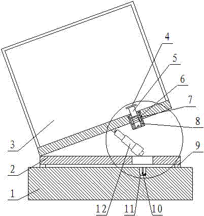
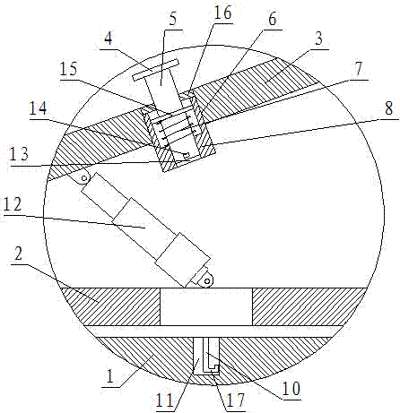
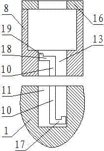
[0017] Such as figure 1 , figure 2 with image 3 As shown, a crane cab locking device includes a fixed seat 1, a rotating seat 2 is provided on the upper surface of the fixed seat 1, and the rotating seat 2 is rotationally connected to the fixed seat 1. The upper surface of the swivel base 2 is hinged with a hydraulic rod 12, the top end of the hydraulic lever 12 is hinged on the lower surface of the cab 3, and the left side of the cab 3 and the swivel base 2 are connected by hinge A mounting hole 6 is provided on one side of the hydraulic rod 12 on the bottom surface of the cab 3, a cylinder 8 is provided in the mounting hole 6, and a sliding plate 15 is slidably provided in the cylinder 8, so The center of the sliding plate 15 is provided with a sliding rod 5, the top of the cylinder 8 is provided with an end cover 16, and the sliding rod 5 above the sliding plate 15 is slidably connected to the end cover 16. The sliding rod 5 An operating handle 4 is fixed at the top end o...

Embodiment 2

[0020] Such as figure 1 , figure 2 with image 3 As shown, a crane cab locking device includes a fixed seat 1, a rotating seat 2 is provided on the upper surface of the fixed seat 1, and the rotating seat 2 is rotationally connected to the fixed seat 1. The upper surface of the swivel base 2 is hinged with a hydraulic rod 12, the top end of the hydraulic lever 12 is hinged on the lower surface of the cab 3, and the left side of the cab 3 and the swivel base 2 are connected by hinge A mounting hole 6 is provided on one side of the hydraulic rod 12 on the bottom surface of the cab 3, a cylinder 8 is provided in the mounting hole 6, and a sliding plate 15 is slidably provided in the cylinder 8, so The center of the sliding plate 15 is provided with a sliding rod 5, the top of the cylinder 8 is provided with an end cover 16, and the sliding rod 5 above the sliding plate 15 is slidably connected to the end cover 16. The sliding rod 5 An operating handle 4 is fixed at the top end o...


PUM


Abstract

The invention relates to a locking device of a crane cab. The locking device comprises a fixed base. A rotating base is arranged on the upper surface of the fixed base. A hydraulic rod is hinged to the upper surface of the rotating base. The top end of the hydraulic rod is hinged to the lower surface of the cab. An installation hole is formed in the portion, on one side of the hydraulic rod, on the bottom face of the cab. A cylinder is arranged in the installation hole. A slide plate is arranged in the cylinder in a sliding manner. A slide rod is arranged at the center of the slide plate in apenetrating manner. A compression spring is arranged around the portion, below the slide plate in the cylinder, of the slide rod. The bottom end of the slide rod is arranged in a through hole in the center of the bottom end face of the cylinder in a sliding manner. Grooves with the diameter the same as the inner diameter of the through hole are formed in the positions, corresponding to the throughhole, on the upper surface of the fixed base. Vertical slide grooves are formed in the corresponding positions on the side walls of the through hole and the grooves. Limiting blocks are arranged in the vertical slide grooves in a sliding manner. The limiting blocks are fixed to the positions, close to the bottom end, on the side wall of the slide rod. The locking device has the beneficial effectsthat the structural design is reasonable, pitching and rotating of driving can be locked, and use is safe and reliable.

Description

Technical field [0001] The invention belongs to the technical field of cranes, and specifically relates to a crane cab locking device. Background technique [0002] With the needs of economic development and national construction, cranes have developed rapidly in recent years. Due to the actual needs of the project, in order to enable the operators in the cab to have a good vision and avoid unnecessary personal injuries and property losses , Most crane cabs are designed to be rotatable and pitchable structure, but the uncontrolled rotation of the turntable during the driving of the crane will affect the balance of the crane, and even cause the crane to roll over. Therefore, we need to be in the process of driving the crane A locking structure is provided for the cab of the crane. In the prior art, the common forms of the locking structure of the crane turntable are mechanical locker and hydraulic locker. The structure of the mechanical locker is relatively simple, but it can only...

Claims


Application Information

Patent Timeline
IPC IPC(8): B66C13/52B66C13/54
CPCB66C13/52B66C13/54
Inventor 丁一董彦波董爱军
Owner 德马科起重机械有限公司
Why Eureka
Eureka Blog
Learn More