
Assisted bike driving system and application thereof

A technology for power-assisted bicycles and driving systems, which is applied in the directions of rider driving, vehicle components, vehicle gearboxes, etc., which can solve the problems of power consumption and riding effort, and achieve the effect of light travel and increased travel use probability

Inactive Publication Date: 2018-05-08
尹伟承
View PDF0 Cites 2 Cited by
  • Summary
  • Abstract
  • Description
  • Claims
  • Application Information

AI Technical Summary

Problems solved by technology

Although this traditional drive system is simple in structure, it is very laborious when riding, especially when the bicycle is driving on a gentle slope.
People need to step on the bicycle pedal harder, and the force will drive the chain on the outer circle of the gear plate from the power point in the center of the gear plate to drive the bicycle forward, or have to push the bicycle to walk, which consumes more people. more force

Method used


Image

  • Assisted bike driving system and application thereof
  • Assisted bike driving system and application thereof
  • Assisted bike driving system and application thereof

Examples


Embodiment 1

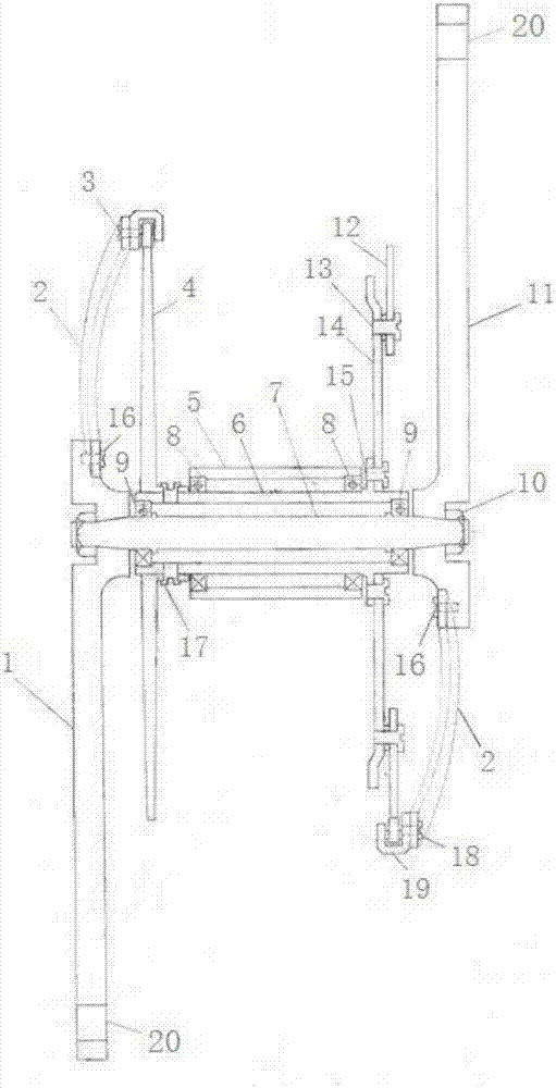
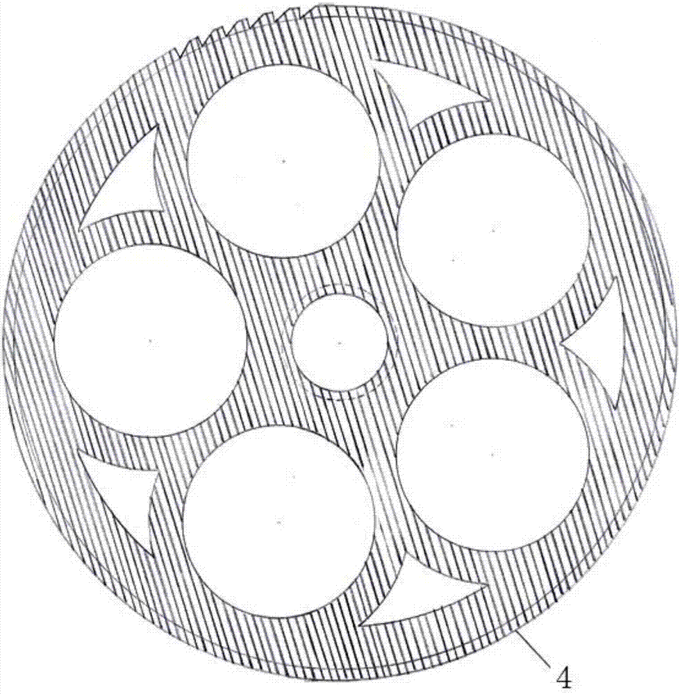
[0049] Such as figure 1As shown, this embodiment provides a power-assisted bicycle drive system, including a crank and a crank shaft 7, a transmission shaft 6, and a fixed shaft 5 that are sequentially fitted from the inside to the outside; Fixedly connected with the driven chain toothed disc 14, the outer circle of the driven chain toothed disc 14 is also connected with the driving gear ring 12; the two ends of the crank shaft 7 are respectively fixedly connected with two described cranks, and one end of the crank is connected with the pedal, The other end is connected with a lever power transmission, one end of one lever power transmission drives the outer circle of the active chainring to rotate through a ratchet driver and a pawl, and one end of the other lever power transmission is driven by a ratchet driver and a pawl The outer circle of the driving gear ring rotates.

[0050] Specifically, as Figure 9 As shown, the two ends of the crankshaft 7 are installed with two ...

Embodiment 2

[0055] This embodiment provides a power-assisted bicycle driving system, the structure of which is as described in Embodiment 1, the difference is that: one end of the left lever power transmitter 2 and the extended end of the crank 1 form a 45° inclined angle and are fixed by Screw connection, the other end is driven by the ratchet drive and the pawl to drive the outer circle of the active toothed plate 4 to rotate; one end of the lever power transmission device 2 on the right is at a 45° inclined angle with the extended end of the crank and is connected by a set screw, the other end The outer circle of the active gear ring 12 is driven to rotate by the ratchet driver and the pawl.

[0056] The semicircular lever power transmitter is in the shape of an arc semicircle, the arc radius is 36-93mm, and the rotation radius is 39-135mm. The semicircular lever power transmitter and the crank are inclined at an angle of about 45 degrees to save labor. The ratchet drive It is U-shaped...

Embodiment 3

[0060] This embodiment provides a power-assisted bicycle driving system, which is basically the same in structure as Embodiment 1, but cancels the driving chainring 4, the driving ring 12, the ratchet driver 19 and the pawl, including the crank and the sequential assembly from the inside to the outside. crank shaft, transmission shaft, fixed shaft; one end of the transmission shaft is fixedly connected with the chainring of the driven chain; One end of one lever power transmitter is fixedly connected with the other end of the drive shaft, and one end of the other lever power transmitter is fixedly connected with the toothed plate of the driven chain.

[0061] Specifically, the two ends of the crankshaft 7 are respectively equipped with two cranks, i.e., the left crank 1 and the right crank 11, by fixing screws 10. Both the left crank 1 and the right crank 11 have pedal mounting holes 20, Easy to install pedals. Between the crankshaft 7 and the transmission shaft 6 , between t...


PUM


Abstract

The invention relates to an assisted bike driving system and an application thereof. The assisted bike driving system includes cranks and crank shafts, a transmission shaft and a fixing shaft which are sequentially installed from the inside to the outside in a sleeved mode; one end of the transmission shaft is fixedly connected with a driven chain toothed disc; and two ends of the crank shaft areseparately and fixedly connected two of the cranks, one ends of the cranks are connected with pedals and the other ends of the cranks are connected with two lever force transmission machines, and oneof the lever force transmission machines is fixedly connected with the transmission shaft and the other lever force transmission machine is fixedly connected with the driven chain toothed disc. The assisted bike driving system improves a driving form of a traditional bike, a force point of the cranks and external circles of a driving toothed disc and a driving toothed ring is in a slant and labor-saving angle of 45 degree, and the lever force transmission machines drive an external circle of the chain toothed disc to rotate according to the lever principle. Compared with normal bikes, cranks use the center of a toothed disc as power point and then use the center point to drive a chain of an external circle of a toothed disc to rotate, and the assisted bike driving system can save a large amount of external acting force.

Description

technical field [0001] The invention relates to a power-assisted bicycle driving system and its application, belonging to the technical field of bicycles. Background technique [0002] As a convenient, energy-saving, environmentally friendly and cheap bicycle, although it has been widely used in people's lives, it needs people's two feet to step on the bicycle pedals hard in use, so that the bicycle can move forward. Once the distance is far away or the slope section is encountered, the physical strength will be exhausted, especially for the elderly or people with poor physique, and the physical exhaustion will appear even more, thereby limiting the wider application of bicycles. [0003] The traditional bicycle drive system is that the crank and the crankshaft are directly connected to the center point of the chain gear plate. When riding, people need to step on the bicycle pedal to make the crankshaft rotate, and the crankshaft uses the center point of the gear plate as th...

Claims


Application Information

Patent Timeline
Patent Type & Authority Applications(China)
IPC IPC(8): B62M3/00B62M9/00B62M1/00
CPCB62M3/00B62M1/00B62M9/00
Inventor 尹伟承
Owner 尹伟承
Learn More