
Voltage control circuit, headphone type detection configuration circuit, driving circuit and method

A technology of voltage control circuit and configuration circuit, which can be used in earphone/earphone accessories, electrical components, transducer acoustic response prevention, etc., and can solve problems such as poor hearing of audio equipment

Active Publication Date: 2019-09-20
深圳芯智汇科技有限公司
View PDF8 Cites 0 Cited by
  • Summary
  • Abstract
  • Description
  • Claims
  • Application Information

AI Technical Summary

Problems solved by technology

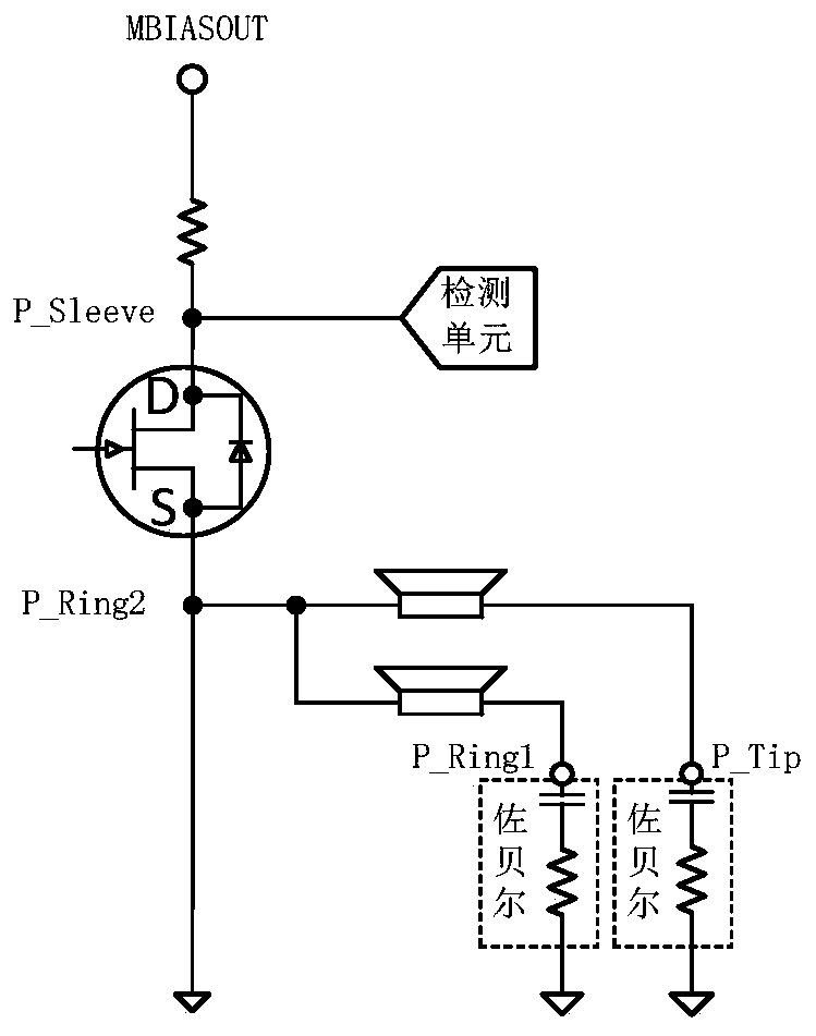
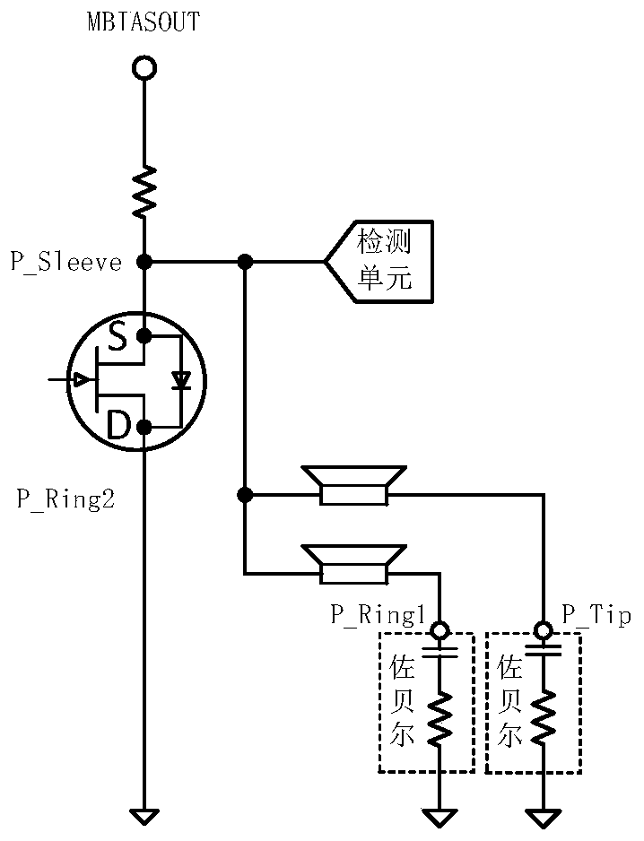
When the audio device detects the type of four-segment earphone inserted, if a positive voltage is applied to both ends of the microphone of the earphone, such as figure 2 As shown, it is the equivalent circuit diagram at this time, and the Zobel circuit is not turned on at this time; if the reverse voltage is applied to both ends of the microphone of the earphone, as shown in image 3 As shown, it is the equivalent circuit diagram at this time. At this time, the Zobel circuit is turned on, which generates an instantaneous current, and then makes the earphone inserted into the audio device emit a "Pop-Click" noise, making the Poor hearing from audio equipment

Method used


Image

  • Voltage control circuit, headphone type detection configuration circuit, driving circuit and method
  • Voltage control circuit, headphone type detection configuration circuit, driving circuit and method
  • Voltage control circuit, headphone type detection configuration circuit, driving circuit and method

Examples


Embodiment Construction

[0052] In order to facilitate the understanding of the present invention, the present invention will be described more fully below with reference to the associated drawings. Preferred embodiments of the invention are shown in the accompanying drawings. However, the present invention can be embodied in many different forms and is not limited to the embodiments described herein. On the contrary, the purpose of providing these embodiments is to make the disclosure of the present invention more thorough and comprehensive.

[0053] It should be noted that when an element is referred to as being “disposed on” another element, it may be directly on the other element or there may also be an intervening element. When an element is referred to as being "connected to" another element, it can be directly connected to the other element or intervening elements may also be present.

[0054] Such as Figure 4 As shown, it is a structural diagram of an embodiment of the headphone driving cir...


PUM


Abstract

The invention relates to a voltage control circuit and method, an earphone type detection configuration circuit and method and an earphone drive circuit. The voltage control circuit is equipped with an input node VIN and an output node VOUT. The input node VIN supplies a stable voltage to the voltage control circuit. The output node VOUT outputs a slowly rising or slowing reducing voltage.

Description

technical field [0001] The invention relates to the field of earphones, in particular to an earphone type detection configuration circuit, a drive circuit with the detection configuration circuit, a voltage control circuit in the detection process and a method thereof. Background technique [0002] Commonly used headphones can be divided into three-segment earphones (not shown) and four-segment earphones (such as Figure 4 Middle earphone 12), the definitions of the three terminals of the three-section earphone plug are respectively: the tip (Tip) is connected to the left channel, the middle ring (Ring) is connected to the right channel, and the end (Sleeve) is grounded. The four terminals of the four-section headphone plug have two standard definitions. The first is the CTIA standard based on the United States: the tip (Tip) connects to the left channel, the middle ring 1 (Ring1) connects to the right channel, and the middle ring 2 (Ring2) is grounded, and the end (Sleeve) ...

Claims


Application Information

Patent Timeline
Patent Type & Authority Patents(China)
IPC IPC(8): H04R1/10H04R3/02H04R29/00
Inventor 朱双兵付增功陈云
Owner 深圳芯智汇科技有限公司
Learn More