
Multi-camera array shooting device with adjustable spacing

A shooting device and multi-camera technology, applied in the field of 3D shooting, can solve the problems of large shooting limitations, high cost, and long cycle, and achieve the effect of convenient operation and simple structure

Active Publication Date: 2018-05-04
GUANGDONG IND TECHN COLLEGE
View PDF7 Cites 6 Cited by
  • Summary
  • Abstract
  • Description
  • Claims
  • Application Information

AI Technical Summary

Problems solved by technology

The current status of the 3D industry is: 3D glasses-free stereoscopic displays are fully mature, and there are many related products, such as glasses-free 3D advertising machines, glasses-free 3D mobile phones, and glasses-free 3D game consoles, etc., but the glasses-free 3D content required by the industry is very scarce.
Existing glasses-free 3D content mostly uses software such as 3dmax and Maya to model, which is difficult to produce, has a long cycle, slow speed, and high cost. There are very few real shots, which cannot meet the needs of the rapid development of the industry. High-quality, fast and convenient Acquisition and shooting equipment
[0003] The early multi-viewpoint acquisition and shooting tools were mostly stereo cameras, such as three- and four-lens film stereo cameras. There have also been dedicated multi-lens digital stereo cameras. However, due to the fixed lens spacing of this camera, the lens spacing cannot be adjusted according to the shooting situation. Shooting is very limited
In the prior art, there is also a single-lens camera mounted on a guide rail to move and shoot, but it can only shoot still life, and it is impossible to collect high-quality multi-viewpoint content in occasions where the subjects such as people and exterior scenes are always shaken.

Method used


Image

  • Multi-camera array shooting device with adjustable spacing
  • Multi-camera array shooting device with adjustable spacing
  • Multi-camera array shooting device with adjustable spacing

Examples


Embodiment Construction

[0017] Combine below Figure 1 to Figure 3 The present invention is described further.

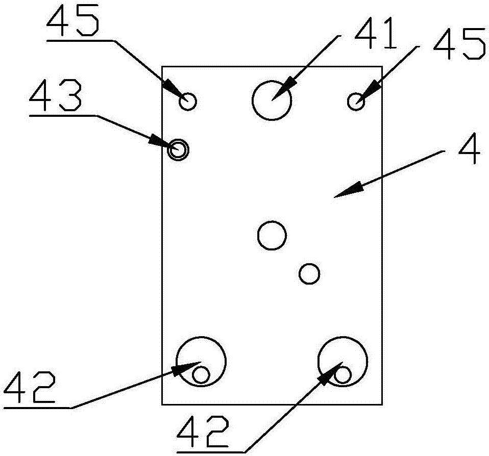
[0018] The multi-camera array photographing device with adjustable spacing includes multiple cameras 1, and the number of cameras 1 in this embodiment is eight. Each of the cameras 1 is directly or indirectly arranged on the guide rail 3 through a corresponding slider 4 , and each of the sliders 4 is arranged in series along the guide rail 3 in sequence. The camera 1 can be directly installed on the slider 4 , or the camera 1 can be installed on the L-shaped mounting plate 2 , and then the L-shaped mounting plate 2 can be fixed on the slider 4 . In this embodiment, the installation method of the camera is the latter. The guide rail 3 is installed on the square tube aluminum profile. To strengthen the rigidity of the guide rail, it can be fastened to the square tube aluminum profile by multiple screws. When using the multi-camera array shooting device, the square tube aluminum profile can...


PUM


Abstract

The invention discloses a multi-camera array shooting device with adjustable spacing. The multi-camera array shooting device with adjustable spacing comprises multiple cameras; each camera is arrangedon a guide rail through sliding blocks; each sliding block is provided with an X-type hinging component; each X-type hinging component comprises two hinged rods; the intersection of the hinged rods is an X-hinged point; the X-hinged point is arranged at the side surface of each sliding block; the corresponding hinged rods between two adjacent X-type hinging components are hinged; each sliding block is provided with at least a stop screw; and after each stop screw is tightly screwed, the bottom thereof is connected with the guide rail in a supporting manner. As multiple X-type hinging components are designed to compose a linkage structure, the intersection angle of the other X-type hinging components can be adjusted synchronously as long as one X-type hinging component is changed, and thespacing of each sliding block is further adjusted and same spacing of two adjacent sliding blocks is kept; as the stop screw is designed on each sliding block, all the sliding blocks can be fixed as long as two sliding blocks are fixed by the stop screws.

Description

technical field [0001] The invention relates to the technical field of 3D shooting, in particular to a multi-camera array shooting device with adjustable spacing. Background technique [0002] The difficulty that glasses-free 3D must solve in order to truly enter ordinary families is the collection and production of glasses-free 3D content. Real shot glasses-free 3D content production requires multi-viewpoint acquisition, also known as dense viewpoint technology, which is commonly used with 4, 6, 8, 10 or even up to 24 viewpoints. The more viewpoints, the more difficult it is to shoot, and the higher the cost of the corresponding shooting equipment. The current status of the 3D industry is: 3D glasses-free stereo displays are fully mature, and there are many related products, such as glasses-free 3D advertising machines, glasses-free 3D mobile phones, glasses-free 3D game consoles, etc., but glasses-free 3D content needed by the industry is very scarce. Existing glasses-fr...

Claims


Application Information

Patent Timeline
Patent Type & Authority Applications(China)
IPC IPC(8): H04N13/243
CPCY02E10/50
Inventor 谢俊国谢亚萱
Owner GUANGDONG IND TECHN COLLEGE
Learn More