Corner nailing machine

A technology of brad nailing machine and transmission mechanism, which is applied in nailing tools, U-shaped nailing tools, manufacturing tools, etc. It can solve the problems of low production efficiency, high defective rate, cumbersome operation, etc., and achieve production efficiency High, meet the effect of automatic production

Pending Publication Date: 2018-05-01
南通嘉奇钣金科技有限公司
View PDF7 Cites 0 Cited by
  • Summary
  • Abstract
  • Description
  • Claims
  • Application Information

AI Technical Summary

Problems solved by technology

This leads to low production efficiency, cumbersome operation, and a high rate of defective products; therefore, it is urgent to propose a brad nailing machine that is conducive to automatic design and has a pass rate that meets production requirements.

Method used


Image

  • Corner nailing machine
  • Corner nailing machine
  • Corner nailing machine

Examples


Embodiment Construction

[0021] Specific embodiments of the present invention will be described below in conjunction with the accompanying drawings.

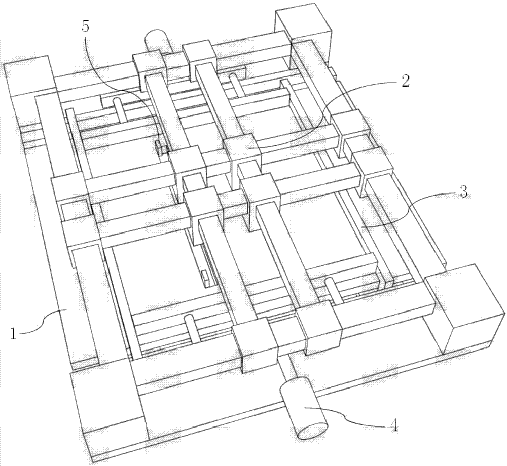
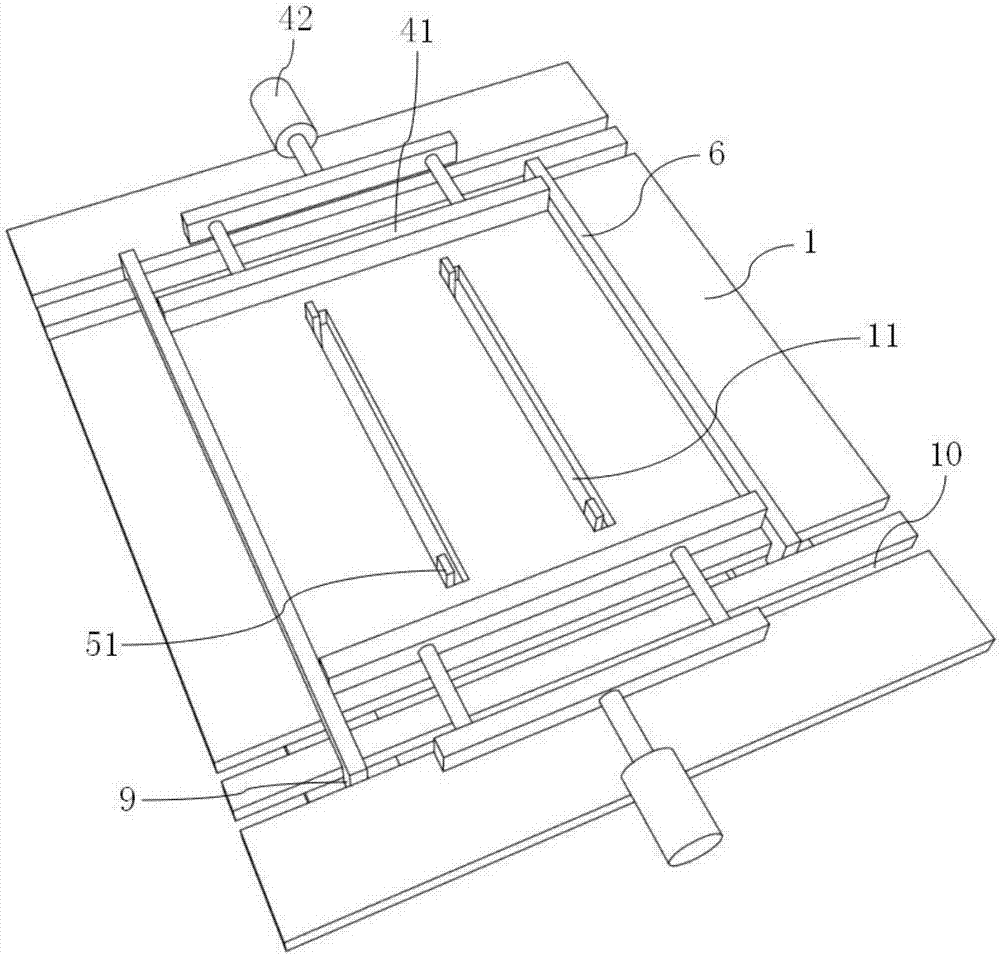
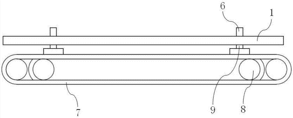
[0022] Such as Figure 1 to Figure 5 As shown, it is a brad nailing machine of the present invention, which includes a working surface 1 and a nail output device 2 for nailing a workpiece to be processed on the working surface 1. The feeding mechanism includes a belt conveying mechanism 3, a push plate feeding mechanism 4 arranged on both sides of the belt conveying mechanism 3 perpendicular to the belt conveying direction, and a positioning mechanism 5 arranged on the working surface 1. The belt conveying mechanism 3 is provided with two positioning The baffle 6 and the positioning baffle 6 are respectively slidably arranged on the working surface 1 , the push plate feeding mechanism 4 is arranged between the two positioning baffles 6 , and the positioning mechanism 5 is arranged between the two push plate feeding mechanisms 4 .

[0023] The belt tran...


PUM


Abstract

The invention provides a corner nailing machine and relates to corner nailing machinery. The corner nailing machine comprises a working face and a nail outlet device, wherein the nail outlet device isused for nailing a to-be-machined part positioned on the working face; an automatic feeding and discharging mechanism is arranged on the working face and comprises a belt transfer mechanism, push plate feeding mechanisms and a positioning mechanism; the push plate feeding mechanisms are perpendicular to a belt transfer direction and are respectively arranged on two sides of the belt transfer mechanism; the positioning mechanism is arranged on the working face; two positioning baffles are arranged on the belt transfer mechanism and respectively arranged on the working face in a sliding manner;the push plate feeding mechanisms are arranged between the two positioning baffles; and the positioning mechanism is arranged between the two push plate feeding mechanisms. The corner nailing machinedisclosed by the invention is capable of realizing automatic feeding and discharging and meeting automatic production needs and has high production efficiency.

Description

technical field [0001] The invention relates to a brad nailing machine, in particular to a brad nailing machine. Background technique [0002] At present, when people are producing photo frames, the existing brad nailing machine needs to manually put the materials into a suitable position, and align the proper position according to the experience of the workers, and then activate the nail output device to drive the brad nails into the corners of the photo frame. This leads to low production efficiency, cumbersome operation, and a high rate of defective products; therefore, it is urgent to propose a brad nailer that is conducive to automatic design and has a pass rate that meets production requirements. Contents of the invention [0003] In order to solve the above technical problems, the present invention provides a brad nailing machine, which can realize automatic material feeding and discharging, meet the needs of automatic production, and have high production efficiency...

Claims


Application Information

Patent Timeline
IPC IPC(8): B27F7/05
CPCB27F7/05
Inventor 成程
Owner 南通嘉奇钣金科技有限公司
Why Eureka
Try Eureka