


Quick Research
Generate reliable direction feasibility study reports for your R&D in just a few steps.

Technical Q&A
Discover and master advanced knowledge NOW. Basics, ideas, possibilities, all at once.

Find Solutions
As an expert in R&D theories, this can generate solutions to your technical problems instantly.

Evaluate Feasibility
Analyze your overall solution with one click, know your potential R&D risks in advance.

Monitor Landscape
Get weekly tech updates, stay abreast of the latest tech innovations and key insights.
Continuous battery cooling system with vertical transfer function
A cooling system and transfer function technology, applied in the direction of lead-acid batteries, climate sustainability, battery pack components, etc., can solve the problem that the effective space is not fully and reasonably utilized, affecting production efficiency, and battery cooling time is limited, etc. Problems, to achieve the effect of small footprint, improve efficiency, and reduce floor space
- Summary
- Abstract
- Description
- Claims
- Application Information
AI Technical Summary
Problems solved by technology
Method used
Image

Examples
Embodiment 1
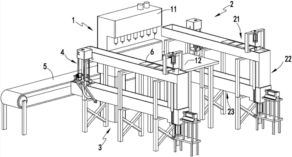
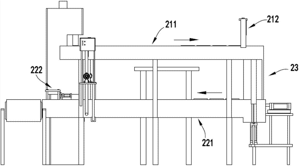
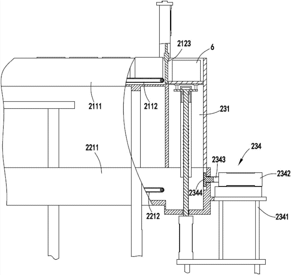
[0047] Such as figure 1 , figure 2 , image 3 , Figure 4 , Figure 5 , Image 6 , Figure 7 , Figure 8 , Figure 9 with Figure 10 As shown, a battery continuous cooling system with vertical transfer function includes an acid adding part 1, the acid adding part 1 is used to add acid to the battery 6; a first cooling delivery part 2, the first cooling The conveying part 2 is arranged on one side of the acid adding part 1; and the second cooling conveying part 3 is arranged on the other side of the acid adding part 1;
[0048] Both the first cooling conveying part 2 and the second cooling conveying part 3 are used to cool the battery 6 that has completed acid addition while conveying, and the first cooling conveying part 2 and the second cooling conveying part 3 both include an upper conveying Mechanism 21, be arranged on the following conveying mechanism 22 below the upper conveying mechanism 21 and be arranged between the upper conveying mechanism 21 and the lower ...
Embodiment 2
[0070] Such as figure 1 , figure 2 , image 3 , Figure 4 , Figure 5 , Image 6 , Figure 7 , Figure 8 , Figure 9 with Figure 10 As shown, the components that are the same as or corresponding to those in the first embodiment are marked with the corresponding reference numerals in the first embodiment. For the sake of simplicity, only the differences from the first embodiment will be described below. The difference between the second embodiment and the first embodiment is: further, a cooling transfer device 4 is also provided between the upper conveying mechanism 21 and the lower conveying mechanism 22, and the cooling transfer device 4 is used to transfer the lower conveying mechanism The water in 22 is transferred to the upper conveying mechanism 21 and the water is cooled during the transfer process. The cooling transfer device 4 includes a water pump 41 and a cooling tower 42. The suction pipe 43 of the water pump 41 communicates with the end of the water chann...
PUM
 Abstract
Description
Claims
Application Information
 - R&D Engineer
- R&D Manager
- IP Professional
- Industry Leading Data Capabilities
- Powerful AI technology
- Patent DNA Extraction
Browse by: Latest US Patents, China's latest patents, Technical Efficacy Thesaurus, Application Domain, Technology Topic, Popular Technical Reports.
© 2024 PatSnap. All rights reserved.Legal|Privacy policy|Modern Slavery Act Transparency Statement|Sitemap|About US| Contact US: help@patsnap.com