A control method for improving the flexibility of a thermal power unit

A technology of thermal power units and control methods, which is applied in the direction of mechanical equipment, engine components, machines/engines, etc., can solve problems such as difficult realization of actual processes on site, unstable renewable energy sources, and poor stability of power grids, etc., to achieve load and balance Internet problems, broad commercialization prospects, and the effect of convenient control

Active Publication Date: 2020-01-31
NORTHEAST DIANLI UNIVERSITY
View PDF3 Cites 0 Cited by
  • Summary
  • Abstract
  • Description
  • Claims
  • Application Information

AI Technical Summary

Problems solved by technology

Problems such as the depletion of non-renewable energy sources and environmental pollution have become increasingly prominent. Countries are striving to find a stable and sufficient energy supply. In recent years, renewable energy power generation technologies such as wind energy and solar energy have developed rapidly, and related technologies have also been greatly improved. Large-scale renewable energy The power generation load needs to be connected to the grid urgently. Renewable energy itself has instability, volatility and uncertainty. Flexibility Needs Rapid Improvement
[0003] At present, most of the load changes in the flexible control technology of thermal power units using the heat storage characteristics of boilers and steam turbines are small, and it is difficult to meet the requirements when the load command of the grid changes greatly.
In the load coordination control of thermal power units, although the advanced optimal control algorithm can effectively improve the unit load tracking ability in theory, the algorithm structure is relatively complicated, and it is difficult to realize the actual process on site.
There is no complete, effective and general method for improving the control technology of thermal power unit flexibility

Method used


Image

  • A control method for improving the flexibility of a thermal power unit
  • A control method for improving the flexibility of a thermal power unit
  • A control method for improving the flexibility of a thermal power unit

Examples


Embodiment Construction

[0047] The following combination Figure 1 to Figure 7 The present invention will be further described in detail with specific examples, and the specific examples described here are only used to explain the present invention, and are not intended to limit the present invention.

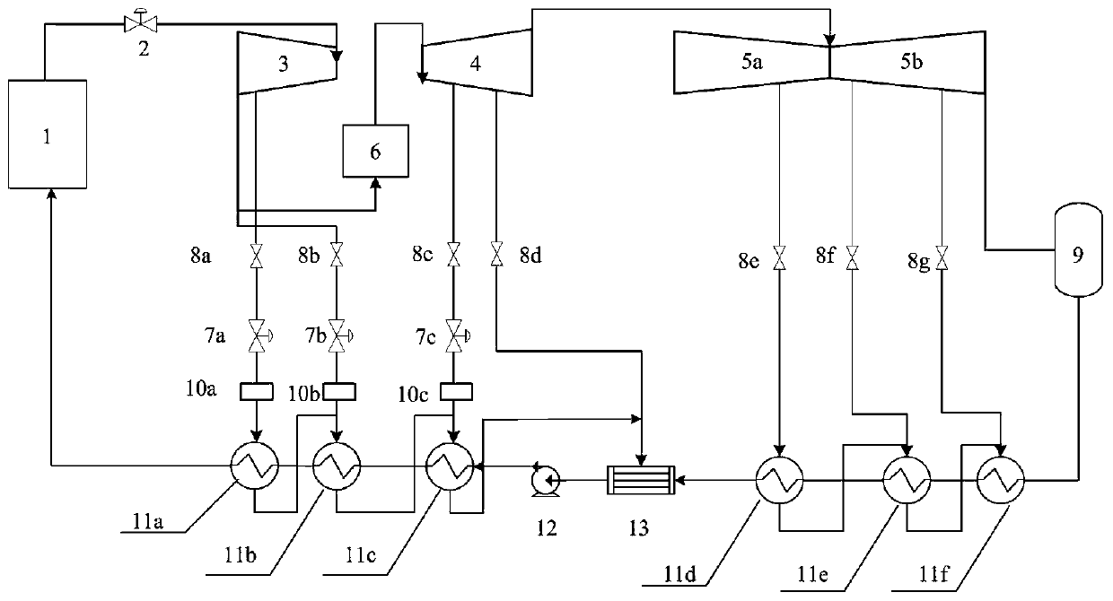
[0048] refer to figure 1 , Both the high-pressure heater and the low-pressure heater of the steam turbine need to extract steam from the steam turbine to heat the boiler feed water. Since the enthalpy of the steam extracted by the high-pressure feedwater heater is relatively high, the ability to change the load of the steam turbine is relatively large. Install an electric regulating valve 7a on the pipeline connecting the steam extraction point of the first stage of the steam turbine to the No. 1 high-pressure feed water heater, and install a differential pressure flowmeter 10a behind the electric regulating valve; Install an electric control valve 7b on the pipeline of No. 1 high-pressure feed water...


PUM


Abstract

The invention discloses a flexible lifting control method for a thermal power generating unit. The flexible lifting control method comprises the following flexible steps of: arranging a throttling device for steam extraction of a steam turbine of a thermal power generating unit; acquiring a steam extraction flow signal of the steam turbine; and improving control of the thermal power generating unit. The invention discloses a set of perfect thermal power generating unit flexible control technology according to related technical means of wavelet decomposition and steam turbine heat-storage advanced utilization. The flexible lifting control method takes load change capability of the steam turbine, main steam pressure dynamic characteristics and unit integral safety into consideration, improves quick load change capacity of the thermal power generating unit, provides technical support for large-scale grid-connection of power generation of renewable energy sources, and has a wide commercialprospect.

Description

technical field [0001] The invention relates to a thermal power unit load coordination control, and a thermal power unit flexibility improvement control method. Background technique [0002] The flexibility of thermal power units refers to the fact that thermal power units can realize load changes safely, stably and quickly when the load command of the power grid changes frequently and in a large range. Problems such as the depletion of non-renewable energy sources and environmental pollution have become increasingly prominent. Countries are striving to find a stable and sufficient energy supply. In recent years, renewable energy power generation technologies such as wind energy and solar energy have developed rapidly, and related technologies have also been greatly improved. Large-scale renewable energy The power generation load needs to be connected to the grid urgently. Renewable energy itself has instability, volatility and uncertainty. Flexibility needs to be ramped up...

Claims


Application Information

Patent Timeline
Patent Type & Authority Patents(China)
IPC IPC(8): F01D17/00F01D17/24G06N3/00
CPCF01D17/00F01D17/24G06N3/006
Inventor 周云龙王迪杨美孙博刘起超杨宁黄娜常赫
Owner NORTHEAST DIANLI UNIVERSITY
Why Eureka
Try Eureka