


Quick Research
Generate reliable direction feasibility study reports for your R&D in just a few steps.

Technical Q&A
Discover and master advanced knowledge NOW. Basics, ideas, possibilities, all at once.

Find Solutions
As an expert in R&D theories, this can generate solutions to your technical problems instantly.

Evaluate Feasibility
Analyze your overall solution with one click, know your potential R&D risks in advance.

Monitor Landscape
Get weekly tech updates, stay abreast of the latest tech innovations and key insights.
Two-way lateral taking device
A container and initial position technology, applied in hoisting devices, hoisting equipment safety devices, lifting frames, etc., can solve the problems of low efficiency, large work site, bulky and other problems of road-rail transfer, achieve simplified road-rail transfer links, occupy The effect of small space and simplified equipment
- Summary
- Abstract
- Description
- Claims
- Application Information
AI Technical Summary
Problems solved by technology
Method used
Image

Examples
Embodiment 1
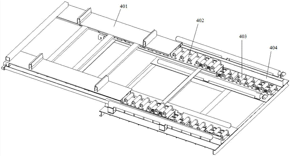
[0073] The two-way side fetching device 4 provided in this embodiment is used to transfer the container 6 on the railway container flat car 7 to the collection truck, and / or transfer the container 6 on the collection truck to the railway container flat car 7; The flat car 7 runs on the railway track under the railway electrification catenary; the two-way side taking device 4 is arranged on the bearing platform 3 between the railway track and the parking position of the collection truck, see the attached Figure 1-9 , The two-way side fetching device 4 includes: a bridge mechanism 402 , a tray mechanism 401 and a lifting mechanism 403 .
Embodiment 1
[0075] The tray mechanism 401 is slidably disposed on the bridge mechanism 402 ; the tray mechanism 401 can slide to a position corresponding to the card loading and unloading device 1 , and / or, slide to a position corresponding to the lifting device 2 . The lifting mechanism 403 is disposed below the bridge mechanism 402 and on the carrying platform 3 , and is used to carry and drive the bridge mechanism 402 and the tray mechanism 401 to rise or fall.
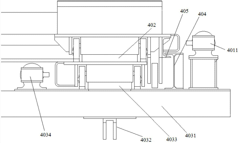
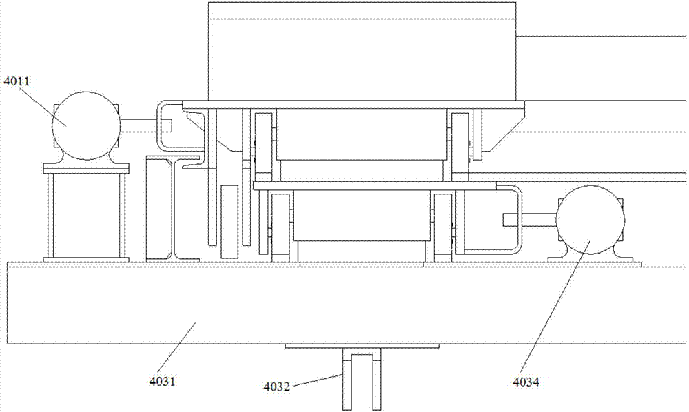
[0076] The lifting mechanism 403 includes: a lifting platform 4031, 4 first telescopic cylinders 4032 and two first slideways 4033 arranged side by side. The 4 first telescopic cylinders 4032 are arranged at the bottom four corners of the lifting platform 4031 for driving the lifting platform 4031 rises or falls, and then adjusts the horizontal height of the container 6 during the transshipment process, so as to adapt to the railway container flat cars 7 of different heights. One end of the first telescopic cylinder 4032 is fi...
Embodiment 2
[0078] See attached Figure 8 , the lifting mechanism 403 also includes: 12 sets of first limit wheels 4035, 6 sets of first limit wheels 4035 are set on one first slideway 4033, and the two first limit wheels 4035 of each group are respectively arranged on the first On both sides of the slideway 4033, 12 sets of first limiting wheels 4035 can ensure that the bridge passing mechanism 402 at the upper end moves along a fixed straight line. There are at least two sets of first limiting wheels 4035 to play the role of fixed limiting in the bridge mechanism 402 .
[0079] A specific first slideway structure is introduced below:
PUM
 Abstract
Description
Claims
Application Information
 - R&D Engineer
- R&D Manager
- IP Professional
- Industry Leading Data Capabilities
- Powerful AI technology
- Patent DNA Extraction
Browse by: Latest US Patents, China's latest patents, Technical Efficacy Thesaurus, Application Domain, Technology Topic, Popular Technical Reports.
© 2024 PatSnap. All rights reserved.Legal|Privacy policy|Modern Slavery Act Transparency Statement|Sitemap|About US| Contact US: help@patsnap.com