
Conveying mechanism for carriers

A transmission mechanism and vehicle technology, applied in the direction of conveyor objects, transportation and packaging, etc., can solve the problems of waste of manpower and time, damage of vehicles, low degree of automation, etc., and achieve the effect of occupying a small space

Active Publication Date: 2018-04-27
FLEXSINE IND TECH SUZHOU CO LTD
View PDF4 Cites 2 Cited by
  • Summary
  • Abstract
  • Description
  • Claims
  • Application Information

AI Technical Summary

Problems solved by technology

[0002] Most of the existing product carrier fixing methods are fixed with screws. Manual clamping and disassembly of the carrier is required. Manual dismantling of the carrier will take a lot of man-hours, and different products need to be equipped with suitable equipment for processing different products. The carrier needs to be replaced every time different products are processed, which wastes a lot of manpower and time to replace the carrier, and according to different carriers, corresponding threaded holes need to be opened on the fixing plate, so that The process is more cumbersome, the degree of automation is low, and the random operation of the workers makes it easy to touch other parts in the processing machine, causing damage to the carrier itself or other parts. It is extremely difficult and unsafe to change the vehicle in the station

Method used


Image

  • Conveying mechanism for carriers
  • Conveying mechanism for carriers
  • Conveying mechanism for carriers

Examples


Embodiment Construction

[0028] The present invention will be further described in detail below with reference to the accompanying drawings. The foregoing and other objectives, features, aspects and advantages of the present invention will become more apparent, so that those skilled in the art can implement them with reference to the text of the description. In the drawings, the shape and size may be exaggerated for clarity, and the same reference numerals will be used in all the drawings to indicate the same or similar parts. In the following description, terms such as center, thickness, height, length, front, back, rear, left, right, top, bottom, upper, and lower parts are based on the orientation or positional relationship shown in the drawings. In particular, "height" corresponds to the size from top to bottom, "width" corresponds to the size from left to right, and "depth" corresponds to the size from front to back. These relative terms are for convenience of description and are generally not inte...


PUM


Abstract

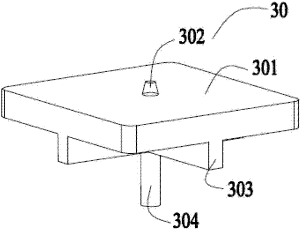
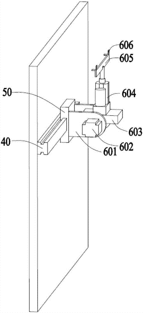
The invention discloses a conveying mechanism for carriers. The conveying mechanism comprises a machine table, a fixed table and two grabbing mechanisms. The fixed table is arranged at the bottom endof the machine table and used for bearing the carriers, the center of the fixed table is provided with a groove, a movable plate matched with the groove is movably arranged in the groove in the longitudinal direction, the two grabbing mechanisms are movably arranged on the two sides of the machine table correspondingly, and the grabbing mechanisms are provided with clamping claws used for grabbingthe carriers. According to the conveying mechanism, the carries are supported to the certain height through the movable plate, then, the carriers are directly conveyed to the position outside the machine table through the grabbing mechanisms, workers can replace the carriers conveniently, the automation degree is improved, and operation safety is ensured.

Description

Technical field [0001] The present invention relates to the field of mechanical equipment. Specifically, the present invention relates to a transmission mechanism for a carrier. Background technique [0002] Most of the existing product carriers are fixed by screws. The mounting and disassembly of the carriers require manual operations. Manual disassembly and disassembly of the carriers will take a lot of man-hours. Different products need to be equipped with their own application. The carrier needs to be replaced every time a different product is processed, which wastes a lot of manpower and time to replace the carrier, and according to different carriers, the fixing plate needs to be opened with corresponding threaded holes, making The process is more cumbersome, the degree of automation is low, and the random operation of the workers makes it easy to touch other parts in the processing machine, causing damage to the carrier itself or other parts, and due to the limited space i...

Claims


Application Information

Patent Timeline
Patent Type & Authority Applications(China)
IPC IPC(8): B65G47/90
CPCB65G47/902
Inventor 徐程东贾卫丰林懿
Owner FLEXSINE IND TECH SUZHOU CO LTD
Learn More