
Debris Cleaner

A technology for cleaning machines and debris, which is applied in metal processing machinery parts, metal processing equipment, maintenance and safety accessories, etc. Effect

Active Publication Date: 2019-04-09
宁波鑫神泽汽车零部件有限公司
View PDF9 Cites 0 Cited by
  • Summary
  • Abstract
  • Description
  • Claims
  • Application Information

AI Technical Summary

Problems solved by technology

[0003] The object of the present invention is to provide a debris cleaning machine to solve the time-consuming and laborious problem of debris recovery in the prior art

Method used


Image

  • Debris Cleaner

Examples


Embodiment Construction

[0021] The following is further described in detail through specific implementation methods:

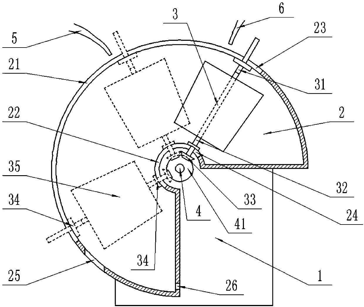
[0022] The reference signs in the drawings of the description include: frame 1, chassis 2, first cylindrical surface 21, second cylindrical surface 22, first through groove 23, second through groove 24, window 25, waste discharge port 26, rotating shaft 3. Free section 31, rotating section 32, first bevel gear 33, limit slider 34, drying bucket 35, driving shaft 4, second bevel gear 41, discharge pipe 5, and drain pipe 6.

[0023] The embodiment is basically as attached figure 1 Shown: the embodiment is basically as attached figure 1 Shown: a debris cleaning machine, including a frame 1 and a chassis 2 with an inner cavity structure fixed on the frame 1, the chassis 2 is a 3 / 4 cylinder, the axis of the chassis 2 is arranged horizontally, the chassis 2 includes a first cylindrical surface 21 and a second cylindrical surface 22, and two sides connecting the first cylindrical surface ...


PUM


Abstract

The invention relates to the technical field of metal cutting devices, in particular to a debris clearing machine. The debris clearing machine comprises a machine frame and a machine box fixed to themachine frame. The machine box is of an inner cavity structure and is a three-fourths cylinder. The axis of the machine box is horizontally arranged. The machine box comprises a first cylinder face, asecond cylinder face and two side faces connected with the first cylinder face and the second cylinder face. The first cylinder face is provided with a first through groove in the circumferential direction of the machine box. The second cylinder face is provided with a second through groove in the circumferential direction of the machine box. A rotating shaft is arranged in the machine box. The rotating shaft is arranged in the radial direction of the machine box. The rotating shaft comprises a rotating section and a free section rotationally connected with the rotating section. The debris clearing machine aims to solve the problem that in the prior art, debris recycling wastes time and effort.

Description

technical field [0001] This patent relates to the technical field of metal cutting equipment, in particular to a debris cleaning machine. Background technique [0002] During the turning process, the workpiece rubs against the tool to generate a large amount of heat, which will cause thermal deformation of the workpiece, which not only affects the machining accuracy of the workpiece, but also affects the clamping and fixing effect of the clamping device on the workpiece. In addition, the turning process A large amount of debris will also be produced in the air, which not only easily causes pollution after splashing, but also has a large waste of resources. Therefore, in production, coolant is often used to cool the workpiece. Coolant is an industrial liquid used in metal cutting and grinding processes to cool and lubricate tools and workpieces. Easy to dilute feature. Metal shavings are intermingled in the used coolant and need to be removed from the coolant and washed fo...

Claims


Application Information

Patent Timeline
Patent Type & Authority Patents(China)
IPC IPC(8): B23Q11/00
CPCB23Q11/0042
Inventor 王健
Owner 宁波鑫神泽汽车零部件有限公司
Learn More