Charging tray mounting structure of silk feeder

An installation structure and a material tray technology are applied in the field of device structures in the production process of pipe piles, which can solve the problems of hidden dangers, affect the production progress, and easily messed up threads, so as to avoid potential safety hazards, ensure the production progress, and not easily mess up the heads. Effect

Inactive Publication Date: 2018-04-27
FUJIAN DADI CONCRETE PILE
View PDF0 Cites 0 Cited by
  • Summary
  • Abstract
  • Description
  • Claims
  • Application Information

AI Technical Summary

Problems solved by technology

The wire loading machine usually includes a material tray, a main shaft, a motor, and a support frame. The main shaft is pivotally connected to the support frame through a bearing. The tail end of the main shaft is connected to the motor through a sprocket and a chain, that is, the motor can drive the main shaft Rotate, and the material tray is set and fixedly installed on the main shaft; the existing material tray is usually fixed on the main shaft by bolts. Although this installation method is simple and easy to operate, it is easy to cause the material tray to be unstable or even fall off from the main shaft. Phenomenon, not only there is a serious safety hazard, but also lead to the easy mess of the thread on the thread, affecting the production progress of the follow-up process

Method used


Image

  • Charging tray mounting structure of silk feeder
  • Charging tray mounting structure of silk feeder
  • Charging tray mounting structure of silk feeder

Examples


Embodiment Construction

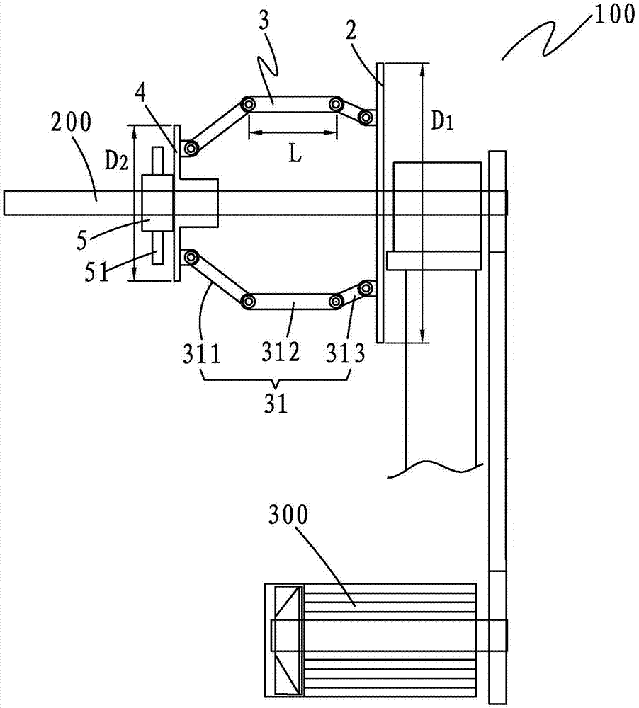
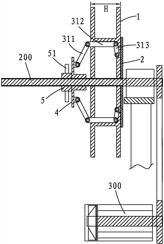
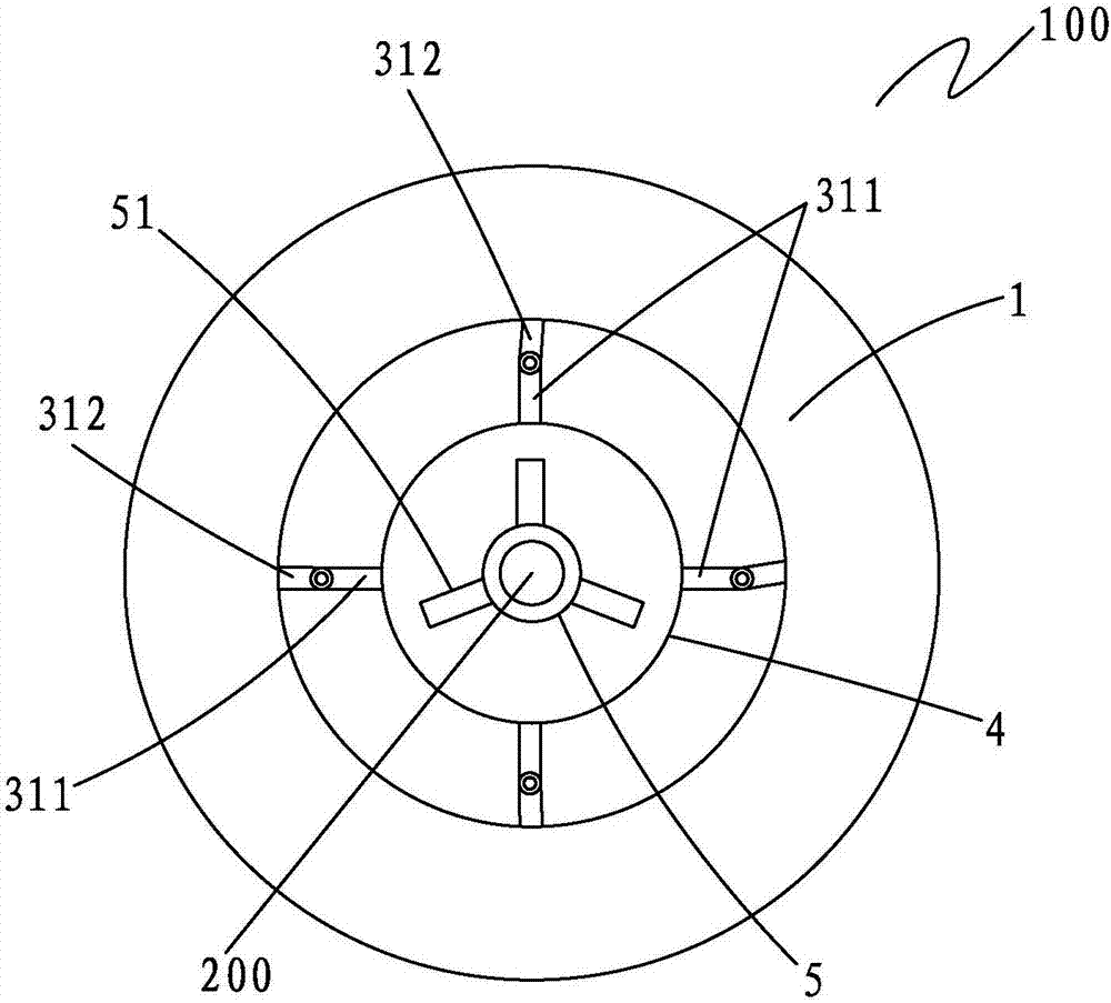
[0017] Please refer to Figure 1 to Figure 3 , a material tray installation structure 100 of a wire feeding machine according to the present invention, comprising a material tray 1, a fixed disc 2 arranged in sequence, a locking frame 3 passing through the material tray 1, a movable disc 4, a A nut 5 matched with the main shaft 200 of the wire loading machine.

[0018] The fixed disc 2 is fixed on the end section of the main shaft 200 of the wire feeding machine, the diameter of the fixed disc 2 is D1, the inner diameter of the material tray 1 is d, D1>d, and the movable disc 4 is slipped on the upper wire On the main shaft 200 of the wire feeding machine, the diameter of the movable disc 4 is D2, D2

[0019] The locking f...


PUM


Abstract

The invention provides a material tray installation structure of a wire feeding machine, which includes a material tray, a fixed disc arranged in sequence, a locking frame passing through the material tray, a movable disc, and a main shaft connected to the wire feeding machine Matching nuts; the locking frame is composed of at least three combined rods, which are evenly distributed around the main shaft of the wire loading machine; each combined rod is composed of a left segment rod and a middle segment rod hinged , and a right segment rod, the left segment rod is fixed on the movable disc, the length of the middle segment rod is greater than the thickness of the tray, and the right segment rod is fixed on the fixed disc. The invention not only ensures the temperature of the installation and avoids potential safety hazards, but also can balance the force on the main shaft of the wire feeding machine after installation, and make the material tray become tighter and tighter when it is rotated.

Description

【Technical field】 [0001] The invention relates to a device structure in the production process of pipe piles, in particular to a material tray installation structure of a wire feeding machine. 【Background technique】 [0002] The wire feeding machine is used in the production process of pipe piles, which is mainly used to draw thick wires into relatively thin wires on site. The wire loading machine usually includes a material tray, a main shaft, a motor, and a support frame. The main shaft is pivotally connected to the support frame through a bearing. The tail end of the main shaft is connected to the motor through a sprocket and a chain, that is, the motor can drive the main shaft Rotate, and the material tray is set and fixedly installed on the main shaft; the existing material tray is usually fixed on the main shaft by bolts. Although this installation method is simple and easy to operate, it is easy to cause the material tray to be unstable or even fall off from the main ...

Claims


Application Information

Patent Timeline
Patent Type & Authority Applications(China)
IPC IPC(8): B21C1/02B21C1/14
CPCB21C1/02B21C1/14
Inventor 周艳文杨金辉林成江雪云徐凯燕博杨佛荣严代富陈智来杨晓彬董伟东
Owner FUJIAN DADI CONCRETE PILE
Why Eureka
Try Eureka