Impeller clearance adjusting device of slurry pump

A gap adjustment device and slurry pump technology, which is applied to wrenches, manufacturing tools, wrenches, etc., can solve the problems of time-consuming and laborious adjustment process, difficult operation, and decreased overall efficiency of slurry pump, etc., to achieve fast and convenient adjustment Effect

Inactive Publication Date: 2022-04-12
河北澳金机械设备有限公司
View PDF0 Cites 0 Cited by
  • Summary
  • Abstract
  • Description
  • Claims
  • Application Information

AI Technical Summary

Problems solved by technology

[0002] At present, the slurry pump is a kind of equipment that generates centrifugal force through the rotation of the impeller to increase the kinetic energy of the solid-liquid mixture, so as to continuously transport the solid-liquid mixture. During the working process of the slurry pump, due to the corrosion of the liquid medium in the solid-liquid mixture , the scouring of small solid particles and the wear of the impeller during high-speed rotation, the gap between the impeller and the lining plate of the pump casing will gradually increase, thereby reducing the overall efficiency of the slurry pump. Therefore, in order to ensure the high efficiency of the slurry pump running, the gap between the impeller and the front guard must be adjusted periodically
[0003] When adjusting the impeller spacing of the slurry pump in the prior art, it is necessary to remove the impeller and its connecting structure, and then use tools and gaskets to adjust the distance between the impeller and the front guard plate, which is difficult to operate and requires The process is time-consuming and laborious

Method used


Image

  • Impeller clearance adjusting device of slurry pump
  • Impeller clearance adjusting device of slurry pump
  • Impeller clearance adjusting device of slurry pump

Examples


Embodiment Construction

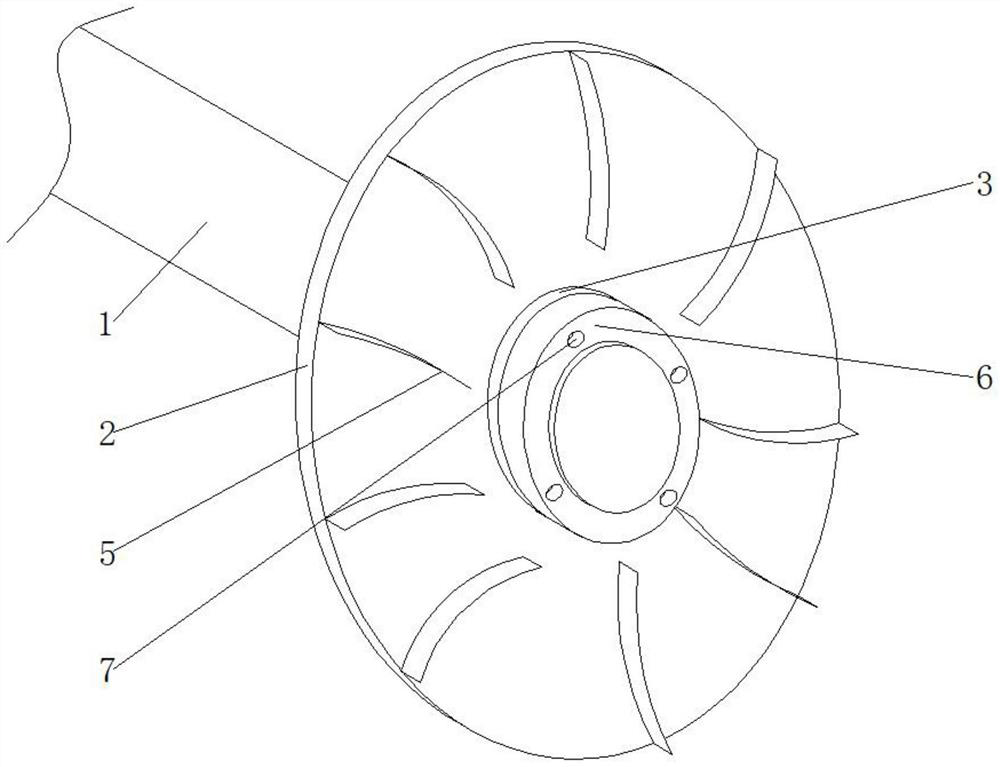
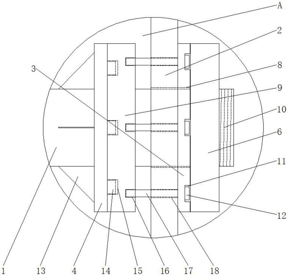
[0030] see Figure 1-7 , the present invention provides a technical solution: a slurry pump impeller 2 clearance adjustment device, including a transmission shaft 1, an impeller 2, a sleeve 3, a counter plate 4 and a wrench 20; the right side surface of the impeller 2 is provided with a blade 5. There are multiple blades 5, and the multiple blades 5 are evenly distributed on the outer ring surface of the impeller 2;

[0031] The impeller 2 is sleeved on the outer ring on the right side of the transmission shaft 1, and the middle surface of the right side of the impeller 2 is fixed with a sleeve 3, and the center surface of the sleeve 3 and the center surface of the impeller 2 are provided with a hole 8, and the sleeve The cylinder 3 is sleeved on the outer ring on the right side of the transmission shaft 1, and the transmission shaft 1 passes through the impeller 2 and the sleeve 3 through the opening 8. The four corners of the surface of the sleeve 3 are provided with grooves...


PUM


Abstract

The invention relates to the technical field of slurry pump impellers, and discloses a slurry pump impeller gap adjusting device which comprises a transmission shaft, an impeller, a sleeve, an abutting plate and a wrench. A plurality of blades are arranged on the surface of the right side of the impeller and evenly distributed on the surface of the outer ring of the impeller, the impeller is arranged on the outer ring of the right side of the transmission shaft in a sleeving mode, a sleeve is fixed to the surface of the middle of the right side of the impeller, and penetrating openings are formed in the center surface of the sleeve and the center surface of the impeller. The right outer ring of the transmission shaft is sleeved with the sleeve. The ring sleeve is arranged on the outer ring of the transmission shaft on the right side of the abutting plate, after the impeller and the sleeve are arranged on the outer ring of the transmission shaft on the right side of the ring sleeve in a sleeving mode, the bolt with the specified length is screwed, penetrates through the impeller and abuts against the interior of the abutting groove, then the nut is screwed on the outer ring on the right side of the transmission shaft, and locking installation of the impeller is achieved; and the impeller clearance can be quickly and conveniently adjusted only by unscrewing the nut and replacing a longer bolt.

Description

technical field [0001] The invention relates to the technical field of slurry pump impellers, in particular to a slurry pump impeller gap adjustment device. Background technique [0002] At present, the slurry pump is a kind of equipment that generates centrifugal force through the rotation of the impeller to increase the kinetic energy of the solid-liquid mixture, so as to continuously transport the solid-liquid mixture. During the working process of the slurry pump, due to the corrosion of the liquid medium in the solid-liquid mixture , the erosion of small solid particles and the wear of the impeller during high-speed rotation, the gap between the impeller and the lining plate of the pump casing will gradually increase, which will reduce the overall efficiency of the slurry pump. Therefore, in order to ensure the high efficiency of the slurry pump In operation, the gap between the impeller and the front guard must be adjusted periodically. [0003] In the prior art, when...

Claims


Application Information

Patent Timeline
Patent Type & Authority Applications(China)
IPC IPC(8): B25B13/50
Inventor 张亚娟夏梦坤张海涛丁昆鹏
Owner 河北澳金机械设备有限公司
Why Eureka
Try Eureka