
Method for controlling shape steel tilting and stacking electromagnets

A control method and electromagnet technology, applied in the direction of electrical program control, sequence/logic controller program control, etc., can solve the problems of channel steel unstacking, affecting the channel steel stacking rhythm, and steel dropping, etc., to improve production. Efficiency and safety effects

Active Publication Date: 2018-04-20
MAANSHAN IRON & STEEL CO LTD
View PDF6 Cites 1 Cited by
  • Summary
  • Abstract
  • Description
  • Claims
  • Application Information

AI Technical Summary

Problems solved by technology

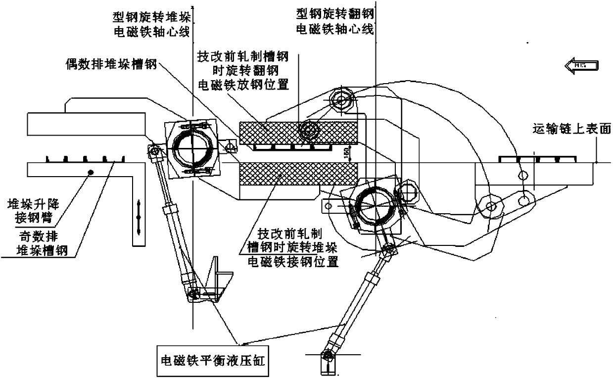
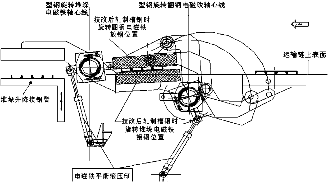
[0011] For this kind of stacking bed channel steel turning control method, in the actual use process, when the length of the channel steel leg is below 70mm, because the leg of the channel steel and the 4# transport chain are connected at the steel position of the rotating turning electromagnet There is still a distance of about 90mm on the upper surface of the channel, and the rows of channel steels with shorter legs will have a large vertical impact on the 4# transportation chain after falling from the steel position of the turning electromagnet. At the same time, the 4# transportation chain will also The same impact force will be produced on the rows of channel steel, so that the row of channel steel will have a larger jump after contacting with the 4# transport chain, which will inevitably make the channel steel on both sides of the row of channel steel and the row of channel steel Separation occurs between the steels. In this case, when the rows of channel steels with short legs are turned over and then stacked by stacking electromagnets, the channel steels on both sides are prone to detachment or even steel drop. Seriously affect the stacking rhythm of channel steel, making it difficult to produce channel steel with short legs

Method used


Image

  • Method for controlling shape steel tilting and stacking electromagnets
  • Method for controlling shape steel tilting and stacking electromagnets
  • Method for controlling shape steel tilting and stacking electromagnets

Examples


Embodiment Construction

[0055] The specific implementation of the present invention will be described in further detail below by describing the embodiments with reference to the accompanying drawings, so as to help those skilled in the art have a more complete, accurate and in-depth understanding of the inventive concepts and technical solutions of the present invention.

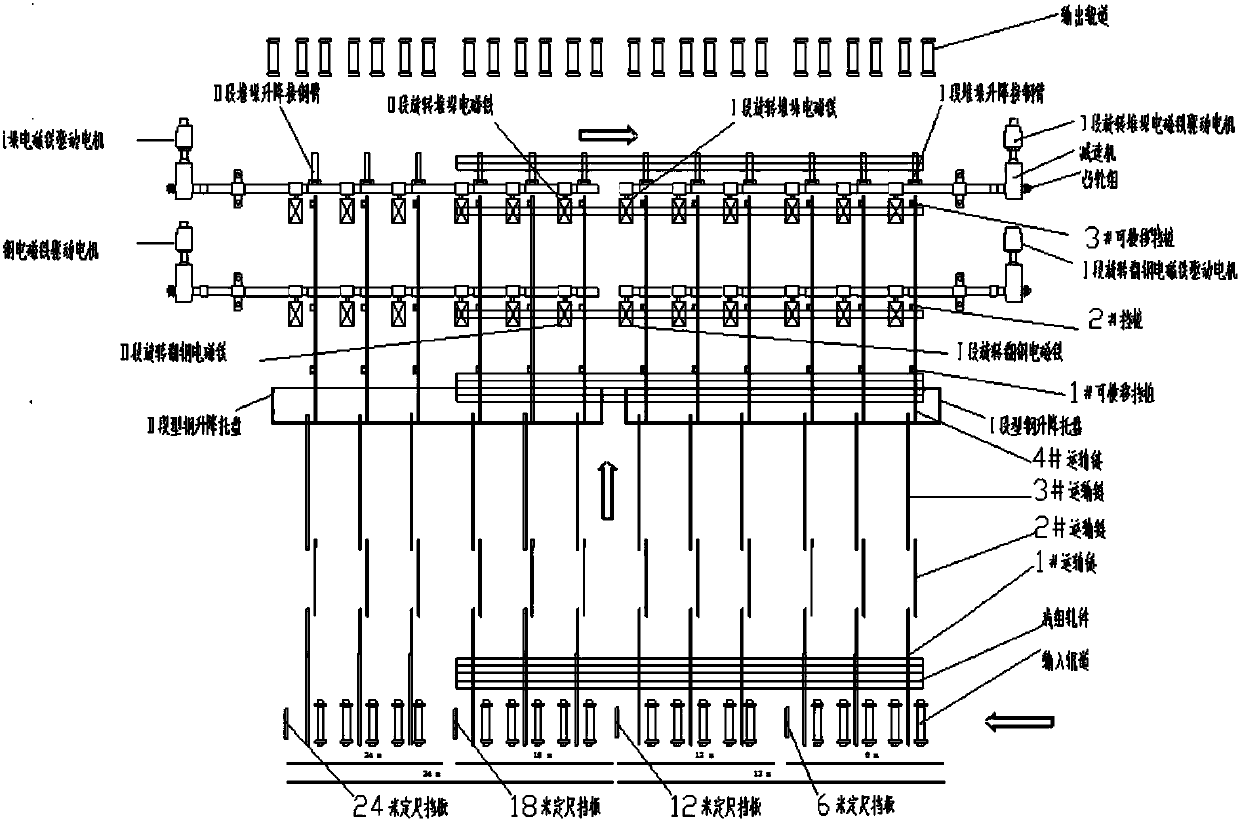
[0056] Such as image 3 The structure of the present invention represented is the arrangement of small H-shaped steel 24m stacking bed process equipment; When the legs of the steel are short and there are rows of channel steels, the channel steels on both sides of the row of channel steels are prone to the problem of destacking or steel dropping. The stacking electromagnet control method can thoroughly avoid the problems that occur when short legs are stacked in rows of channel steels.

[0057] In order to solve the problems existing in the prior art and overcome its defects, and realize the purpose of the invention to completely ...


PUM


Abstract

The invention discloses a method for controlling shape steel tilting and stacking electromagnets. The method comprises four sub control programs, i.e., the shape steel stacking electromagnet rotationenablement control subprogram, the shape steel stacking electromagnet rotation location setting control subprogram, the shape steel tilting electromagnet rotation enablement control subprogram, and the shape steel tilting electromagnet rotation location setting control subprogram. According to the technical scheme, the problem that when an H shape steel stacking lathe stacks a row of channel steelwith short legs and needing to be tilted, the channel steel at two sides in the row of channel steel can deviate from the stack or fall off easily can be thoroughly avoided; the shape steel tilting and stacking normal order and the smooth progress of production can be guaranteed, and the production efficiency and safety are improved.

Description

technical field [0001] The invention belongs to the technical field of section steel turning and stacking mechanical equipment. More specifically, the present invention relates to a control method for section steel turning and stacking electromagnets. Background technique [0002] The small H-shaped steel production line in the prior art has two sectioned steel stacking beds of 18m and 24m, and each sectioned steel stacking bed is composed of two sections respectively. Each section of the section steel stacking bed has the same process equipment settings, respectively, the stacking bed is input into the roller table, several roller table lifts and cut-to-length baffles, and 1#~4# transportation chains (the 1# transportation chain is for lifting and transporting) chain), section steel lifting tray, 1# horizontally movable lifting retaining pile, 2# lifting retaining pile, rotating steel electromagnet, 3# horizontally movable retaining pile, rotating stacking electromagnet, h...

Claims


Application Information

Patent Timeline
IPC IPC(8): G05B19/04
CPCG05B19/04
Inventor 叶光平董长付李健菲尹正华徐洪徐璐高凌云
Owner MAANSHAN IRON & STEEL CO LTD
Learn More