
Hydraulic clamping welding positioner for heavy parts

A welding positioner and hydraulic clamping technology, applied in welding equipment, auxiliary welding equipment, welding/cutting auxiliary equipment, etc., can solve the problems of low robot welding work efficiency and high labor intensity, so as to improve welding efficiency and reduce Labor intensity, fast clamping effect

Active Publication Date: 2020-02-18
SHANDONG LINGONG CONSTR MACHINERY
View PDF4 Cites 0 Cited by
  • Summary
  • Abstract
  • Description
  • Claims
  • Application Information

AI Technical Summary

Problems solved by technology

[0003] The purpose of the present invention is to provide a hydraulic clamping and welding positioner for heavy parts to overcome the high labor intensity and the work efficiency of robot welding caused by the manual clamping of the heavy parts welding positioner in the prior art low defect

Method used


Image

  • Hydraulic clamping welding positioner for heavy parts
  • Hydraulic clamping welding positioner for heavy parts
  • Hydraulic clamping welding positioner for heavy parts

Examples


Embodiment Construction

[0022] The present invention will be further described below in conjunction with accompanying drawing.

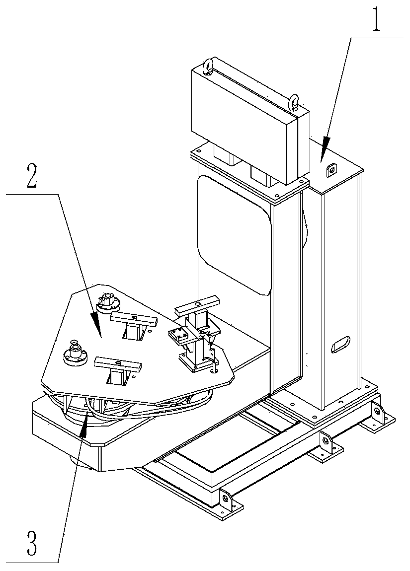
[0023] like figure 1 As shown, a hydraulic clamping welding positioner for heavy parts proposed by the present invention includes a main structure 1 of an L-shaped welding positioner, a clamping body 2 and a transmission mechanism 3 .

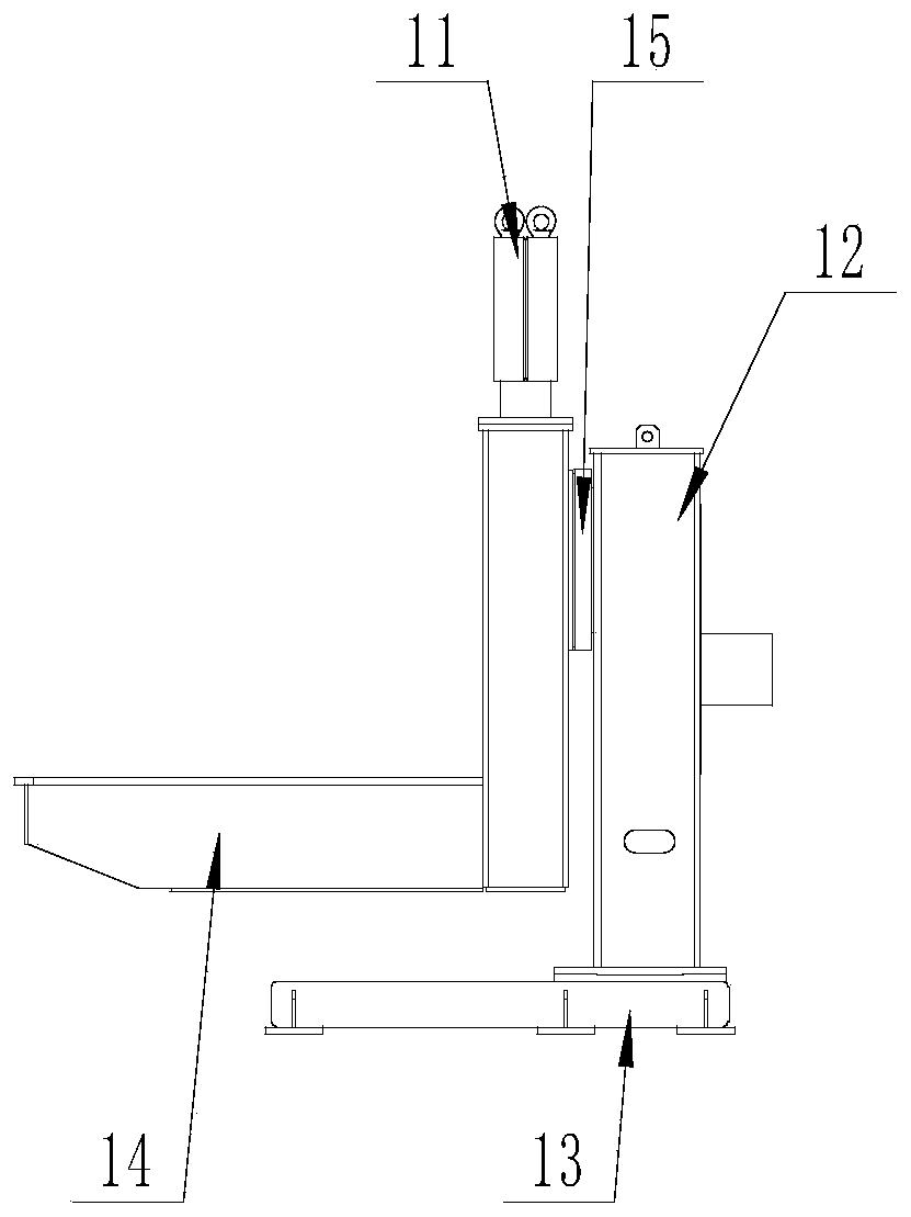
[0024] like figure 2 As shown, the main structure 1 of the L-shaped welding positioner includes a counterweight body 11, a vertical motor cabinet 12, a positioner base 13, an L-shaped arm 14 and a rotary mechanism 15, and the counterweight body 11 is fixed on the L-shaped arm 14 by bolts , the L-shaped arm 14 is connected with the vertical motor cabinet 12 through the slewing mechanism 15, which can realize ±180 ° flipping on the vertical plane, and the vertical motor cabinet 12 is fixed on the positioner base 13 by bolts.

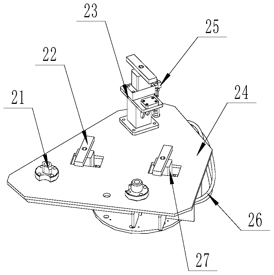
[0025] like image 3 As shown, the clamp body 2 includes a positioning shaft 21, a pressing block 22, a positionin...


PUM


Abstract

The invention discloses a heavy type part hydraulic clamping and welding positioner, and belongs to the field of engineering machinery. The positioner comprises an L-shaped welding positioner main structure, a clamp body and a transmission mechanism. The clamp body comprises a positioning shaft, a pressing block, a positioning base, a clamp body base and a rotary hydraulic oil cylinder. The rotaryhydraulic oil cylinder is fixed to the clamp body base and fixedly connected with the pressing block. The positioning shaft and the positioning base are fixed to the clamp body base respectively, andthe clamp body base is fixed to the L-shaped welding positioner main structure. According to the heavy type part hydraulic clamping and welding positioner, it is ensured that clamping is rapid, efficient and accurate and saves labor in the large workpiece welding process, the product welding efficiency is improved, the transmission mechanism simultaneously achieves the transmission function and the rotation function, and the transmission mechanism has the double functions of load transferring and hydraulic fluid transferring.

Description

technical field [0001] The invention belongs to a construction machinery welding device, in particular to a hydraulic clamping and welding positioner for heavy parts. Background technique [0002] In the field of loader manufacturing, the front frame is an important part of the main structure of the loader. With the promotion of welding robot technology, most companies currently use flexible robot welding systems to weld the front frame. Due to the large size of the front frame itself , the weight is heavy, and it is time-consuming and laborious to perform clamping and positioning on the robot welding positioner. However, the current welding positioner generally adopts the method of manual clamping, and the front frame is fixed on the welding positioner fixture. In fact, the requirement for manual labor intensity is very high, and it also seriously affects the work efficiency of robot welding and reduces the degree of automation of robot welding. Moreover, the current transm...

Claims


Application Information

Patent Timeline
Patent Type & Authority Patents(China)
IPC IPC(8): B23K37/04B23K37/047
CPCB23K37/04B23K37/0443B23K37/047
Inventor 葛福华刘欢程鹏李国坤
Owner SHANDONG LINGONG CONSTR MACHINERY
Learn More