
Automatic positioning device

A positioning device and positioning unit technology, applied in the direction of manufacturing tools, workshop equipment, etc., can solve the problems of object deviation from the original position, inaccurate drilling, hanging tilt, etc., to achieve small body movements, accurate drilling, and not easy to deviate moving effect

Active Publication Date: 2020-12-04
杭州铭赫科技有限公司
View PDF5 Cites 0 Cited by
  • Summary
  • Abstract
  • Description
  • Claims
  • Application Information

AI Technical Summary

Problems solved by technology

[0002] In the process of interior decoration, people often need to punch holes on the wall to hang furniture accessories, lamps or picture frames and other objects. For the sake of beauty, the hanging holes of these objects are generally set on the back, which brings great difficulties to the precise positioning of the hanging position. Generally, it is more common to use a ruler to measure the coordinates of the hanging hole on the back relative to the outer frame of the object. The efficiency is very low, and it is easy to make mistakes and cause the hanging to tilt. Re-drilling holes will cause greater damage to the wall. , there is also a conventional method of manually determining the orientation, drawing the outline of the frame with a pencil, and then measuring the coordinates of the hanging hole with a ruler for positioning. Then when tracing the outline of the frame, the limbs of the movement are relatively large, which will inevitably cause the object to shift from its original position, which will directly lead to the inaccuracy of the final punching

Method used


Image

  • Automatic positioning device
  • Automatic positioning device
  • Automatic positioning device

Examples


Embodiment

[0016] The present invention will be described in further detail below with an automatic positioning device including 4 positioning units, but this does not constitute any limitation to the protection scope of the present invention.

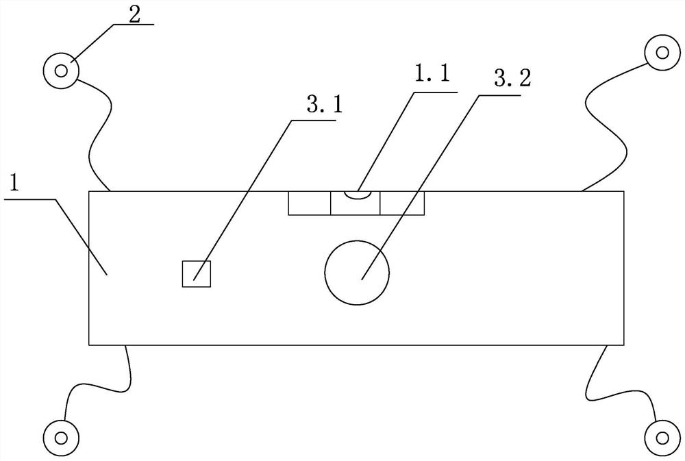
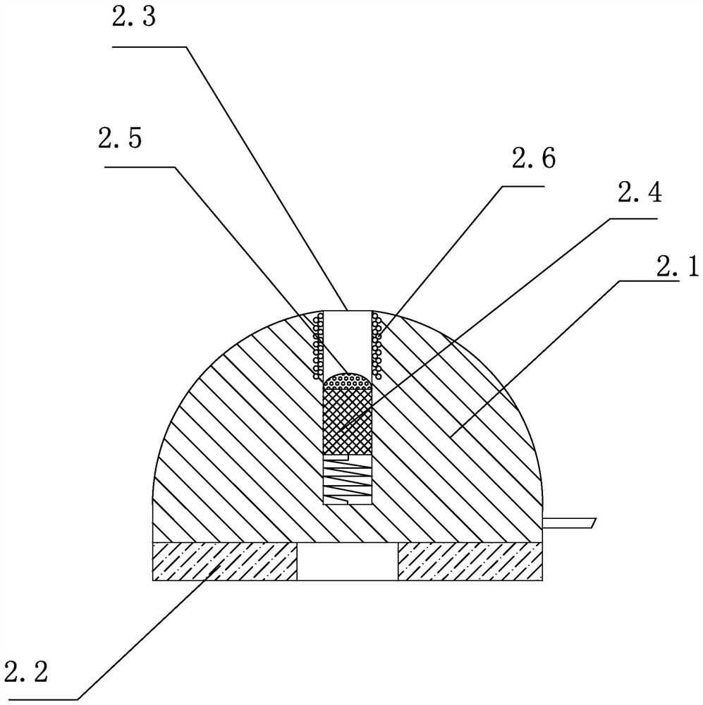
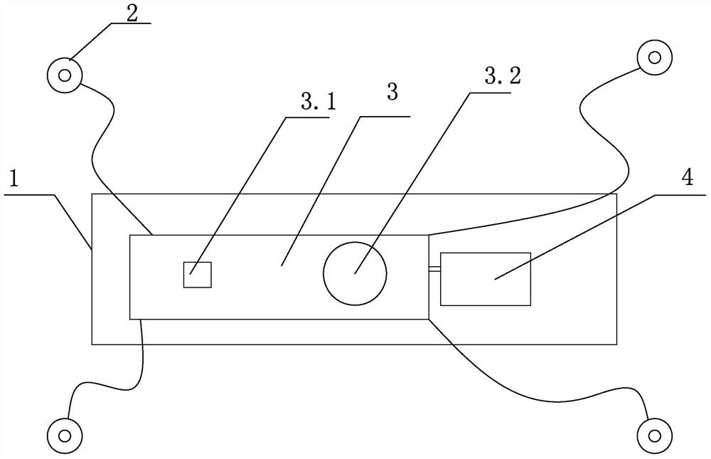
[0017] Such as Figure 1-4 Shown, a kind of automatic positioning device, it comprises cuboid casing 1, the bubble level 1.1 that is located on described cuboid casing 1, and 4 positioning units 2; Described cuboid casing 1 is provided with circuit board 3 and to described cuboid casing 1 The lithium battery 4 powered by the circuit board 3; the cuboid shell 1 is provided with a charging key 3.1 and a start key 3.2 electrically connected to the circuit board 3; the positioning unit 2 is electrically connected to the circuit board 3 through a flexible wire The positioning unit 2 includes a hemispherical body 2.1, the bottom of the hemispherical body 2.1 is pasted with an annular double-sided adhesive 2.2, and the top is coaxially provided with a b...


PUM


Abstract

The invention discloses an automatic positioning device comprising a cuboid shell (1), a bubble level (1.1) arranged in the cuboid shell (1), and a plurality of positioning units (2); the cuboid shell(1) is internally provided with a circuit board (3) and a lithium battery (4) used for power supply for the circuit board (3); the cuboid shell (1) is provided with a charging key (3.1) and a start key (3.2) which are electrically connected to the circuit board (3); the positioning units (2) are electrically connected to the circuit board (3) through flexible wires. The automatic positioning device disclosed by the invention has the advantages of easy use and assistant positioning, so that accurate punching is ensured.

Description

technical field [0001] The invention relates to an automatic positioning device. Background technique [0002] In the process of interior decoration, people often need to punch holes on the wall to hang furniture accessories, lamps or picture frames and other objects. For the sake of beauty, the hanging holes of these objects are generally set on the back, which brings great difficulties to the precise positioning of the hanging position. Generally, it is more common to use a ruler to measure the coordinates of the hanging hole on the back relative to the outer frame of the object. The efficiency is very low, and it is easy to make mistakes and cause the hanging to tilt. Re-drilling holes will cause greater damage to the wall. , there is also a conventional method of manually determining the orientation, drawing the outline of the frame with a pencil, and then measuring the coordinates of the hanging hole with a ruler for positioning. Then, when tracing the outline of the f...

Claims


Application Information

Patent Timeline
Patent Type & Authority Patents(China)
IPC IPC(8): B25H7/04
CPCB25H7/04B25H7/045
Inventor 李丹
Owner 杭州铭赫科技有限公司
Learn More