
Transformer clamp and manufacturing method thereof

A technology of a transformer clip and a manufacturing method, applied in the field of transformers, can solve problems such as eddy current loss of transformer cores, and achieve the effects of small eddy current loss, low magnetic permeability and high resistivity

Inactive Publication Date: 2018-04-13
CSR ZHUZHOU ELECTRIC CO LTD
View PDF2 Cites 0 Cited by
  • Summary
  • Abstract
  • Description
  • Claims
  • Application Information

AI Technical Summary

Problems solved by technology

[0004] The purpose of the present invention is to provide a transformer clamp and its manufacturing method, which can effectively solve the problems such as eddy current loss easily generated in the magnetic field of the transformer core

Method used


Image

  • Transformer clamp and manufacturing method thereof
  • Transformer clamp and manufacturing method thereof
  • Transformer clamp and manufacturing method thereof

Examples


Embodiment Construction

[0024] In order to make the above objects, features and advantages of the present invention more comprehensible, the specific implementation manners of the present invention will be described in detail below in conjunction with the accompanying drawings.

[0025] In the following description, specific details are set forth in order to provide a thorough understanding of the present invention. However, the present invention can be implemented in many other ways than those described here, and those skilled in the art can make similar extensions without departing from the connotation of the present invention. Accordingly, the present invention is not limited to the specific embodiments disclosed below.

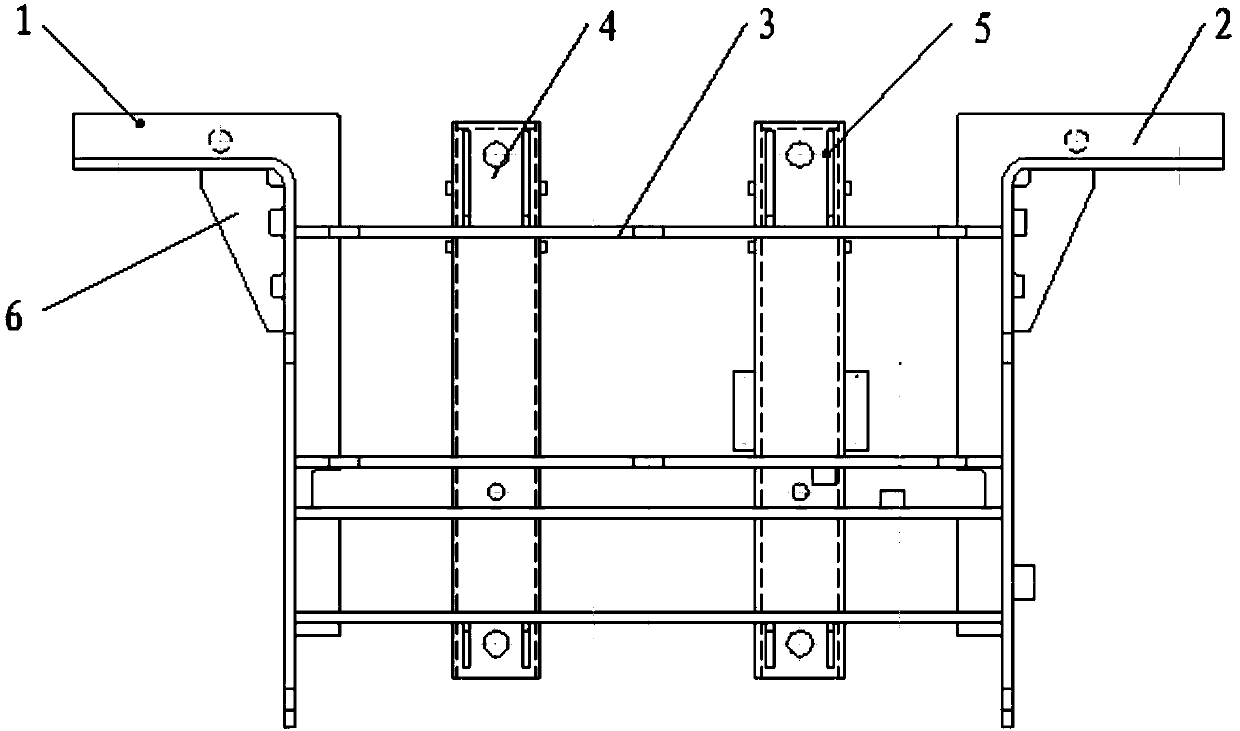
[0026] Please refer to Figure 1-Figure 3 , figure 1 It is a schematic diagram of the front view structure of a transformer clamp provided by a specific embodiment of the present invention; figure 2 A schematic top view structure diagram of a transformer clamp provided for a ...


PUM


Abstract

The invention discloses a transformer clamp. The transformer clamp comprises a left non-magnetic steel side plate and a right non-magnetic steel side plate, a connection plate, a left non-magnetic steel press beam and a right non-magnetic steel press beam, wherein the left non-magnetic steel side plate and the right non-magnetic steel side plate are horizontally and symmetrically arranged, two ends of the connection plate are connected with the left non-magnetic steel press beam and the right non-magnetic steel press beam, and the left non-magnetic steel press beam and the right non-magnetic steel press beam are vertically arranged on the connection plate and are arranged in parallel. The invention also discloses a manufacturing method of the transformer clamp. The manufacturing method comprises the following steps of horizontally arranging the connection plate, and respectively welding the two ends of the connection plate on the left non-magnetic steel side plate and the right non-magnetic steel side plate; and arranging the left non-magnetic steel press beam and the right non-magnetic steel press beam in parallel, and respectively and vertically welding the left non-magnetic steel press beam and the right non-magnetic steel press beam on the connection plate. Since the non-magnetic steel is low in magnetic conductivity and high in resistance rate, the eddy-current loss in a magnetic field is small, and local overheating of a transformer core can be prevented.

Description

technical field [0001] The invention relates to the technical field of transformers, in particular to a transformer clip and a manufacturing method thereof. Background technique [0002] Transformer clamps are mainly used to fix and clamp the transformer core. The existing transformer clamps are mainly welded by Q345E materials, which are prone to eddy current loss in the magnetic field of the transformer core, which will lead to local overheating and affect the normal operation of the transformer. Use, but also reduce the service life of the transformer. [0003] Therefore, how to provide a transformer clip and its manufacturing method to reduce eddy current loss and avoid local overheating is a technical problem that those skilled in the art urgently need to solve. Contents of the invention [0004] The object of the present invention is to provide a transformer clamp and its manufacturing method, which can effectively solve the problems of easy generation of eddy curre...

Claims


Application Information

Patent Timeline
IPC IPC(8): H01F27/26H01F41/00B23P15/00
CPCH01F27/266B23P15/00H01F41/00
Inventor 段永华李爽宋悠全
Owner CSR ZHUZHOU ELECTRIC CO LTD
Learn More