


Quick Research
Generate reliable direction feasibility study reports for your R&D in just a few steps.

Technical Q&A
Discover and master advanced knowledge NOW. Basics, ideas, possibilities, all at once.

Find Solutions
As an expert in R&D theories, this can generate solutions to your technical problems instantly.

Evaluate Feasibility
Analyze your overall solution with one click, know your potential R&D risks in advance.

Monitor Landscape
Get weekly tech updates, stay abreast of the latest tech innovations and key insights.
Locking device and locking method for automotive chassis power testing
A technology of automobile chassis and locking device, which is applied in the field of dynamometer, can solve the problems of low test accuracy of automobile chassis, no setting, easy to produce shaking, etc., to ensure the accuracy, increase the contact surface, and improve the grip strength. Effect
- Summary
- Abstract
- Description
- Claims
- Application Information
AI Technical Summary
Problems solved by technology
Method used
Image

Examples
Embodiment 1
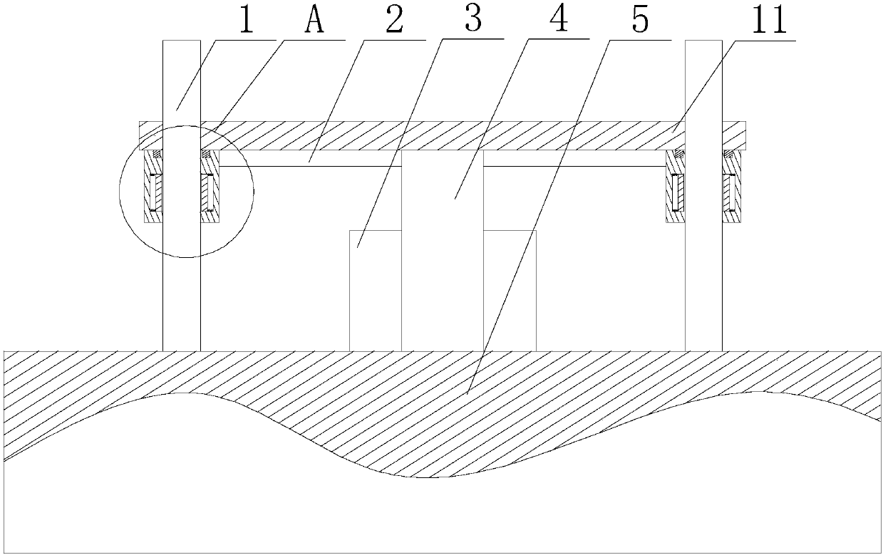
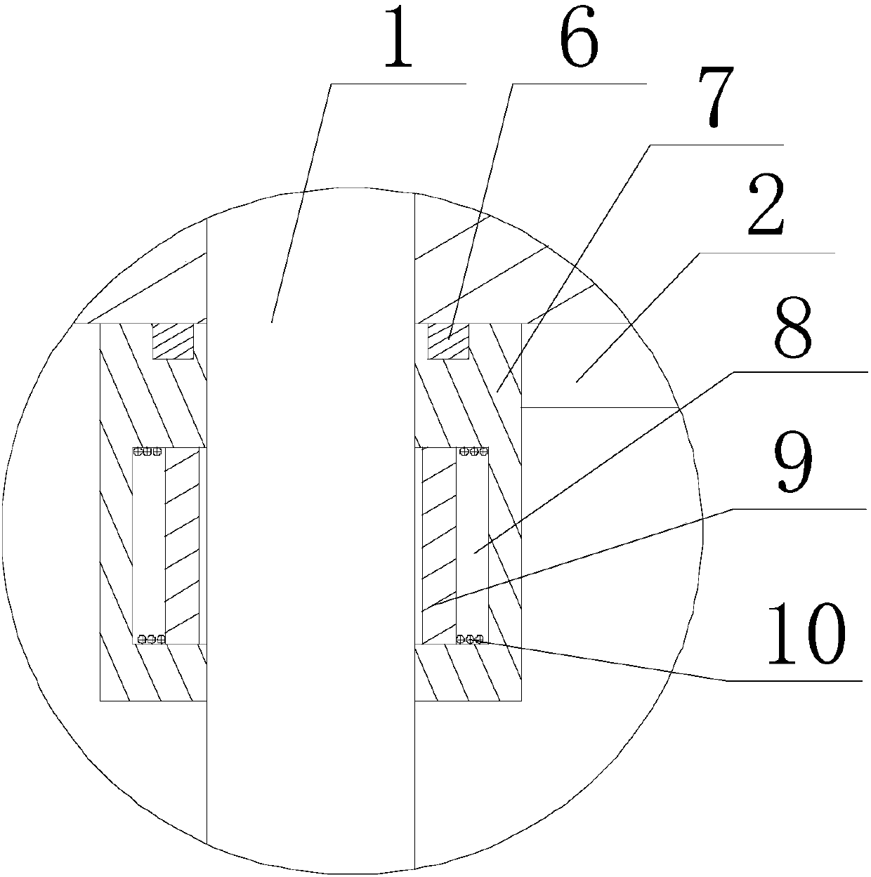
[0025] Such as Figure 1~2As shown, this embodiment includes a rectangular frame 2, and cylindrical follower blocks 7 are respectively fixed at the four right angle points of the rectangular frame 2, and the follower block 7 is sleeved on the positioning rod 1, along the A plurality of grooves 8 are formed on the inner peripheral wall of the follower block 7 in the circumferential direction, and the electromagnet I9 matched with the grooves 8 is slidably arranged in the groove 8, and the outer wall of the electromagnet I9 passes through The spring 10 is connected to the groove bottom of the groove 8, and a pressure sensor is arranged on the upper end surface of the follower block 7, and the pressure sensor communicates with the power switch of the electromagnet I9 through the controller; it also includes two cylinders 3, two The output ends of the cylinder 3 are respectively connected to the bottoms of two parallel sides of the rectangular frame 2 .
[0026] Aiming at the fac...
Embodiment 2
[0033] Such as Figure 1-2 Shown, a kind of locking method that is used for automobile chassis measurement comprises the steps: set a rectangular frame 2 on four positioning rods 1 on the upper end surface of the workbench 5, and set a rectangular frame 2 on the four right angle points of the rectangular frame 2 Tubular follower blocks 7 are respectively provided on the top, and one follower block 7 is respectively sleeved on a positioning rod 1, and cylinders 3 are respectively provided on the bottoms of the two sides parallel to each other on the rectangular frame 2, and the cylinders 3 are used as power output parts. Provide power for the lifting of the rectangular frame 2, that is, when the lifting plate 11 rises or falls, the rectangular frame 2 is always in sync with the lifting plate 11, because the middle part of the bottom surface of the lifting plate 11 is supported by the screw 4, so the lifting plate 11 occurs Shaking is usually at its four right angles, and when t...
PUM
 Abstract
Description
Claims
Application Information
 - R&D Engineer
- R&D Manager
- IP Professional
- Industry Leading Data Capabilities
- Powerful AI technology
- Patent DNA Extraction
Browse by: Latest US Patents, China's latest patents, Technical Efficacy Thesaurus, Application Domain, Technology Topic, Popular Technical Reports.
© 2024 PatSnap. All rights reserved.Legal|Privacy policy|Modern Slavery Act Transparency Statement|Sitemap|About US| Contact US: help@patsnap.com