
A garbage crushing device with rotary centrifugal discharge

A garbage crushing and rotating centrifugation technology, which is applied in grain processing and other fields, can solve the problems of affecting work efficiency, difficulty in taking out garbage, and increasing the burden on workers, etc., and achieves the effect of simple discharging method, simple structure and high working efficiency

Active Publication Date: 2019-06-18
武汉市绿色环保能源有限公司
View PDF4 Cites 0 Cited by
  • Summary
  • Abstract
  • Description
  • Claims
  • Application Information

AI Technical Summary

Problems solved by technology

[0003] The problem of garbage has always troubled people. With the development of society, the amount of garbage is gradually increasing. At present, the more common methods of garbage disposal are landfill and incineration. In the process of garbage landfill and incineration, it is often necessary Smash to improve the degradation rate and incineration efficiency of garbage. The structure of the existing garbage crushing device is relatively simple. After the crushing is completed, it is difficult to take out the garbage, and it is impossible to realize automatic discharge, which affects work efficiency and increases the burden on workers.

Method used


Image

  • A garbage crushing device with rotary centrifugal discharge
  • A garbage crushing device with rotary centrifugal discharge

Examples


Embodiment Construction

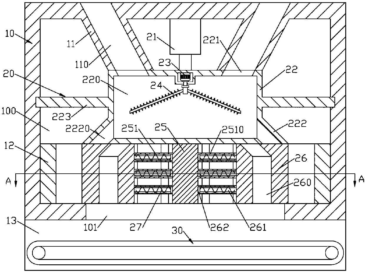
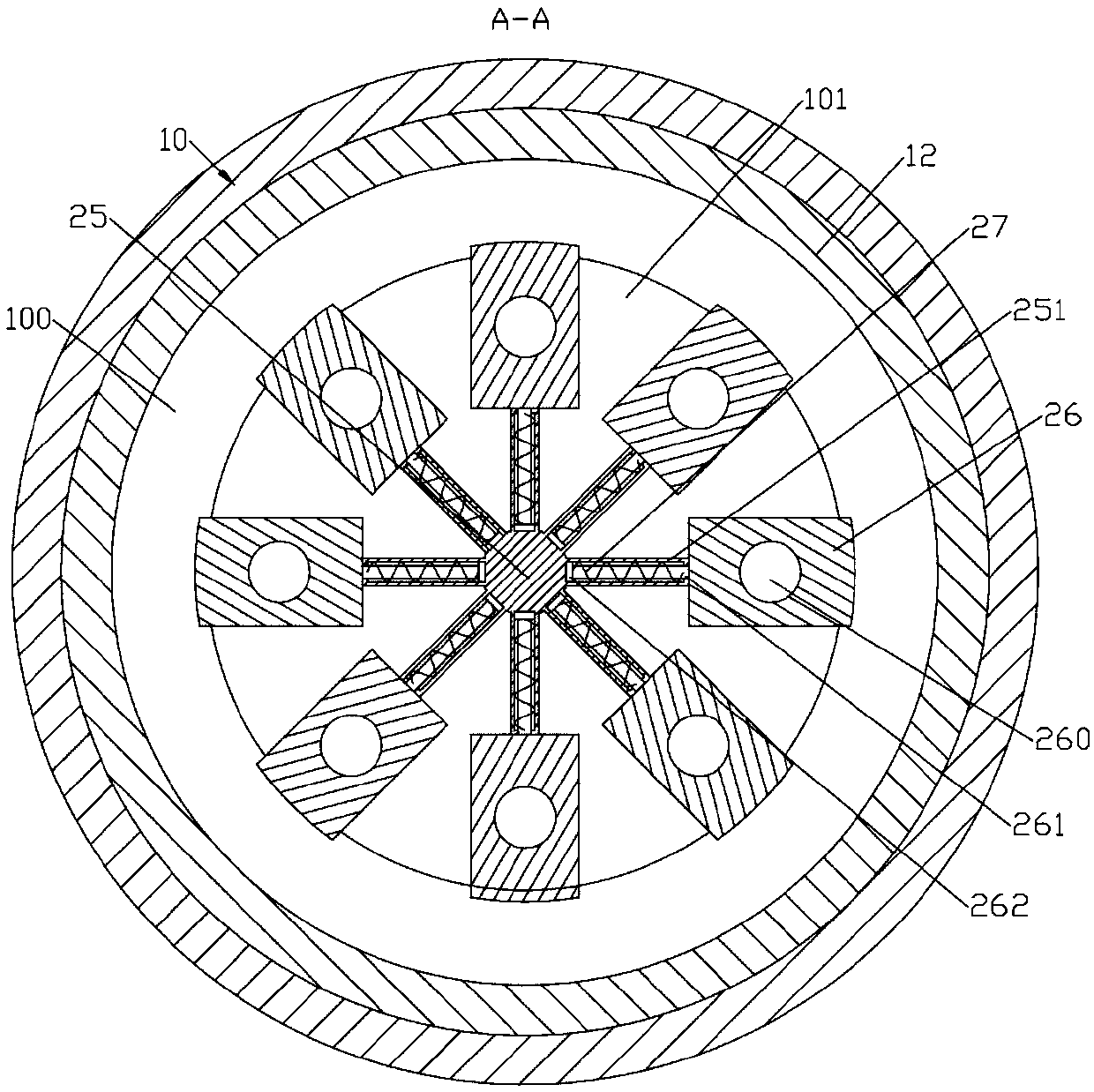
[0016] like figure 1 , figure 2 As shown, a garbage crushing device with rotating centrifugal discharge includes a cylindrical support frame 10, a crushing centrifugal discharge device 20 and a conveyor belt device 30; the interior of the support frame 10 is formed with a cylindrical groove-shaped empty cavity 100; the empty cavity A pair of left-right symmetrical feeding guide pipes 11 are formed on the upper side wall of 100; feeding guide pipes 11 are formed with feeding guide holes 110 penetrating up and down; The crushing and centrifugal discharge device 20 includes a cylindrical crushing tube 22 that is rotated; the inside of the crushing tube 22 is formed with a cylindrical groove-shaped crushing tank 220; the upper side wall of the crushing tank 220 is formed with a feed guide The lower feeding hole 221 which is matched with the hole 110 runs through up and down; the lower end of the outer cylindrical surface of the crushing tube 22 is formed with a number of centrif...


PUM


Abstract

The invention discloses a rotary centrifugal discharge garbage smashing device which comprises a cylindrical supporting frame, a smashing centrifugal discharge device and a conveying belt device. A holler cavity in a shape of a cylinder groove is molded inside the supporting frame, a discharge groove in a shape of a cylinder groove is molded in the lower side wall of the hollow cavity and is through up and down, the smashing centrifugal discharge device comprises a cylindrical smashing barrel in a rotary manner, a smashing groove in a shape of a cylinder groove is molded inside the smashing groove, and a lower feeding hole which is matched with a feeding guide hole and is through up and down is molded in the upper side wall of the smashing groove; and a plurality of centrifugal discharge pipes which are downwards inclined from inside to outside and are circumferentially and evenly distributed are molded in the lower end of the outer cylinder face of the smashing barrel, a plurality ofradial sliding opening and closing blocks distributed circumferentially are arranged on the lower end face of the smashing barrel, the centrifugal discharge pipes can be opened and closed through theopening and closing blocks, a smashing head is rotationally arranged on the upper side wall of the hollow cavity, and the conveying belt device is arranged at the lower end of the supporting frame. The rotary centrifugal discharge garbage smashing device is simple in discharging manner and high in working efficiency.

Description

technical field [0001] The invention relates to the field of environmental protection equipment, in particular to a garbage crushing device for rotary centrifugal discharge. Background technique [0002] Garbage refers to unnecessary or useless solid and fluid substances. In densely populated cities, garbage disposal is a headache. The common practice is to collect them and send them to landfills for landfill treatment, or use incinerators Incineration, but both will cause environmental protection problems, and ending excessive consumption can further reduce the saturation of landfills. Garbage disposal in landfills will not only pollute groundwater and emit odors, but also many cities that can be landfilled The area has become smaller and smaller, and incineration will inevitably produce toxic gases, which are harmful to organisms. Most cities are researching ways to reduce garbage production and encourage resource recycling. On October 14, 1992, Shenzhen, Guangdong Realiz...

Claims


Application Information

Patent Timeline
Patent Type & Authority Patents(China)
IPC IPC(8): B02C18/10B02C18/22
CPCB02C18/0092B02C18/10B02C18/2216
Inventor 林庆芳
Owner 武汉市绿色环保能源有限公司
Learn More