Electric power equipment installation insulating rack

A technology for power equipment and insulating frames, which is applied in the direction of switchgear and electrical components, and can solve the problems of inconvenient operation and use, and inconvenient and stable adjustment of the height of the insulating frame.

Active Publication Date: 2018-04-06
STATE GRID SHANDONG ELECTRIC POWER CO YANTAI CITY FUSHAN DISTRICT POWER SUPPLY CO +1
View PDF4 Cites 4 Cited by
  • Summary
  • Abstract
  • Description
  • Claims
  • Application Information

AI Technical Summary

Problems solved by technology

However, the existing insulating frame is not convenient for stably adjusting its heig

Method used


Image

  • Electric power equipment installation insulating rack
  • Electric power equipment installation insulating rack
  • Electric power equipment installation insulating rack

Examples


Embodiment

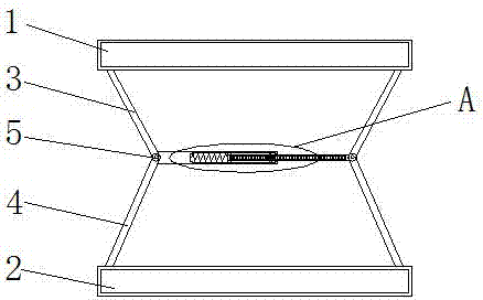
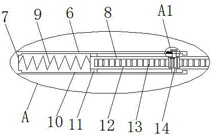
[0024] refer to Figure 1-5 , an insulating frame for installing electrical equipment, including a base 2, an insulating plate 1 is arranged above the base 2, two first connecting rods 4 are installed on the top side of the base 2, and two first connecting rods 4 are installed on the bottom side of the insulating plate 1. The second connecting rod 3, and the two second connecting rods 3 are arranged correspondingly to the two first connecting rods 4 respectively, and one end of the first connecting rod 4 and the corresponding second connecting rod 3 that are close to each other is rotationally connected by a rotating shaft 5 , any one rotating shaft 5 close to the other rotating shaft 5 is rotated with a fixed rod 6, one end of the fixed rod 6 is provided with a sliding groove 7, a sliding rod 8 is slidably installed in the sliding groove 7, and one end of the sliding rod 8 extends To the outside of the sliding groove 7, and the rotation is installed on the corresponding rotat...


PUM


Abstract

The invention discloses an electric power equipment installation insulating rack. The rack herein includes a pedestal which is provided with an insulating plate thereabove. The top side of the pedestal is rotatingly provided with two first connecting rods. The bottom side of the insulating plate is rotatingly provided with two second connecting rods. The two second connecting rods are disposed corresponding to the two first connecting rods. Each first connecting rod is in rotary connection to a corresponding second connecting rod at ends thereof that approach each other via a rotating shaft. One side of random rotating shaft close to the other rotating shaft is rotatingly provided with a fixing lever. One end of the fixing lever is provided with a sliding groove. The sliding groove is slidingly provided with a sliding lever therein. One end of the sliding lever extends to the outside of the sliding groove, and is rotatingly installed at a corresponding rotating shaft. One side of the sliding lever is provided with a placement groove. The placement groove is fixedly provided with a tooth bar therein. According to the invention, the rack herein can easily and fast adjust the height of the insulating plate, and can easily stabilize the height of the insulating plate after the adjustment.

Description

technical field [0001] The invention relates to the technical field of electric equipment, in particular to an insulating frame for installing electric equipment. Background technique [0002] An insulating frame for installing electrical equipment, as a protective and safety equipment for installing electrical equipment, should provide people with a firm, durable, and safe structure to the greatest extent. The existing insulating rack for installing electrical equipment can only serve as a temporary insulation role, and the insulation effect is poor. The prior art does not further expand its function. [0003] The patent with the application number CN201410739895.0 discloses an insulating frame for installing electrical equipment, including insulating plates, terminals, outer covers, and lifting devices. The insulating board is connected to the outer cover through terminals. The outer cover can be stretched, and the height can be adjusted freely. The housing is made of ...

Claims


Application Information

Patent Timeline
IPC IPC(8): H02B3/00
CPCH02B3/00
Inventor 李志杰王金旭隋广胜李建平王建赵伟张楠曲建东王旭东刁训静盖玉俭林训鹏修维红姜晓艳林晓红呼钊功
Owner STATE GRID SHANDONG ELECTRIC POWER CO YANTAI CITY FUSHAN DISTRICT POWER SUPPLY CO
Why Eureka
Try Eureka