Eureka AIR delivers breakthrough ideas for toughest innovation challenges, trusted by R&D personnel around the world.

Paper overturning machine and paper feeding mechanism thereof

A feeding mechanism and feeding technology, applied in the direction of turning objects, thin material processing, object supply, etc., can solve the problems of different paper sizes and weights, difficult paper transmission, and inability to overcome paper weight, etc., to achieve transmission efficiency and transmission. The effect of guaranteeing stability, improving production quality and improving the quality of finished products

Active Publication Date: 2018-04-06
浙江星锋智能设备有限公司
View PDF11 Cites 4 Cited by
  • Summary
  • Abstract
  • Description
  • Claims
  • Application Information

AI Technical Summary

Problems solved by technology

[0003] In the actual use process, it will also be found that the size and weight of the paper are different depending on the batch of paper to be processed. , the friction force generated by the upper conveyor belt c and the lower conveyor belt f on the paper cannot overcome the weight of the paper itself, and the paper will be difficult to transmit

Method used


Image

  • Paper overturning machine and paper feeding mechanism thereof
  • Paper overturning machine and paper feeding mechanism thereof
  • Paper overturning machine and paper feeding mechanism thereof

Examples


Embodiment 1

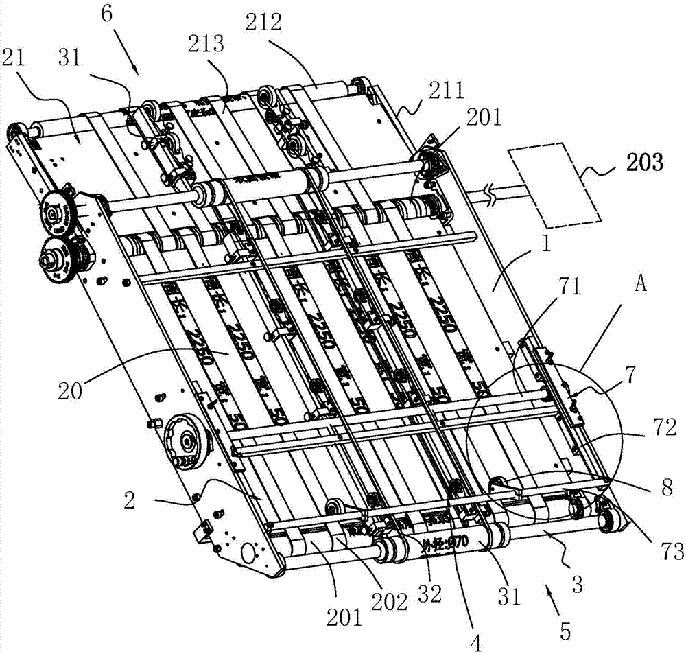
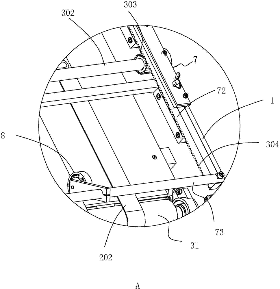
[0049] A paper feeding mechanism, see figure 1 , including a feed frame 1, a feed main transmission part 2 and a feed secondary transmission part 3 are installed in the feed frame 1, the feed secondary transmission part 3 is located above the feed main transmission part 2, and the feed main transmission part 2 and the feed auxiliary transmission part 3 will form a feed gap 4, and the two ends of the feed gap 4 are the paper feed end 5 and the paper discharge end 6 respectively; the paper enters the feed gap 4 from the paper feed end 5, and the paper The upper surface of the paper will be squeezed by the feeding auxiliary conveying part 3, and the lower surface of the paper will also be squeezed by the feeding main conveying part 2, and through the joint action of the feeding main conveying part 2 and the feeding auxiliary conveying part 3 , the paper will be transported from the paper input end 5 to the paper output end 6 in one direction.

[0050] Wherein, the feeding main c...

Embodiment 2

[0059] A paper turning machine, see Figure 4 , including a frame 9, a drive unit 10, a paper turning mechanism 11, a transport mechanism 18, a paper transport mechanism 22, and a paper feeding mechanism as in Embodiment 1. The paper feeding mechanism is located on one side of the paper turning mechanism 11, and the paper feeding The feeding mechanism transmits the paper to be turned over to the paper turning mechanism 11, and the paper turning mechanism 11 turns over the paper to be turned over one side, the transport mechanism 18 is located under the paper turning mechanism 11, and the paper transport mechanism 22 is located at the position where the transport mechanism 18 is away from the paper turning mechanism. Below the mechanism 11, the feeding mechanism transfers the overturned paper to the paper turning mechanism 11, and the paper will be passed out from the paper turning mechanism 11, and the paper transmission mechanism 22 will place the paper on the transport mechan...

Embodiment 3

[0075] Embodiment three: the difference with embodiment two is:

[0076] see Figure 4 as well as Figure 10 , on the second conveying belt 183, be provided with the contact area 19 that is used to catch the paper that falls from the discharge end 17 at the first time, and the horizontal sliding table 26 is provided with the damping wheel 30, and the damping wheel 30 It is used to resist against the lower belt wall of the second transmission belt 183 opposite to the contact area 19 and close to the paper turning mechanism 11; during use, when the paper falls on the contact area 19 of the second transmission belt 183, the damping wheel 30 is also just in place. Against the lower belt surface of the second transmission belt 183 , sufficient supporting force of the second transmission belt 183 can be provided.


PUM


Abstract

The invention discloses a paper overturning machine and a paper feeding mechanism thereof. According to the main technical scheme, the paper feeding mechanism comprises a feeding rack, a feeding mainconveying component and a feeding subsidiary conveying component; the feeding main conveying component comprises two or more feeding rollers, feeding conveying belts and a feeding driving motor, wherein the feeding rollers are rotatably connected to the feeding rack, the feeding conveying belts are mounted among the feeding rollers, and the feeding driving motor is used for driving the feeding rollers to rotate; the feeding subsidiary conveying component comprises two or more compression rollers and compression conveying belts, wherein the compression rollers are rotatably connected to the feeding rack, and the compression conveying belts are mounted among the compression rollers; a feeding gap is formed between each compression conveying belt and the corresponding feeding conveying belt,wherein each feeding gap allows paper to enter therein. The two ends of each feeding gap are a paper inlet end and a paper outlet end correspondingly. The paper feeding mechanism further comprises a paper compression portion, wherein the paper compression portion is located at the side of the paper inlet ends and comprises paper compression wheels, wherein the paper compression wheels are mountedon the feeding rack and used for tightly pressing the paper to the feeding conveying belts. By means of the paper feeding mechanism, the to-be-overturned paper can be stably conveyed into the paper overturning mechanism; and conveying efficiency and conveying stability are fully guaranteed.

Description

technical field [0001] The invention relates to a paper turning device, in particular to a paper turning machine and a paper feeding mechanism thereof. Background technique [0002] In the technological process of the paper industry, the paper feeding mechanism is relatively common, and its structure is as attached figure 1 The paper feeding mechanism shown includes an upper conveying part a and a lower conveying part d. The upper conveying part a is composed of two upper conveying rollers b and an upper conveying belt c connected between the two upper conveying rollers b. The transmission part d is composed of two lower transmission rollers e and a lower transmission belt f connected between the two lower transmission rollers e. There is a certain gap g between the upper transmission belt c and the lower transmission belt f. The paper to be fed will enter the gap g, the upper transmission belt c will rub against the upper surface of the paper, and the lower transmission be...

Claims


Application Information

Patent Timeline
Patent Type & Authority Applications(China)
IPC IPC(8): B65H15/00B65H5/02B65H5/22
CPCB65H5/02B65H5/222B65H15/00
Inventor 周贤清周禹彤蒋文贤林仲逸许修强
Owner 浙江星锋智能设备有限公司
Why Eureka
Eureka Blog
Learn More