Material drying device

A drying device and material technology, applied in the direction of drying gas arrangement, wood drying, drying solid materials, etc., can solve the problems of uneven drying degree of finished products, inability to dry effectively, and different sizes, etc., to achieve fast drying speed and uniform drying The effect of thorough correction of curvature

Inactive Publication Date: 2018-03-30
湖州南浔丽学木制品厂
View PDF0 Cites 0 Cited by
  • Summary
  • Abstract
  • Description
  • Claims
  • Application Information

AI Technical Summary

Problems solved by technology

Among them, although the continuous and automatic production efficiency of tunnel microwave drying is relatively high, it has relatively high requirements for the single shape, density (humidity), placement on the conveyor belt and the total amount of drying of the wood to be dried, which must be met. The shape and density (humidity) of the monomers are similar and placed evenly, otherwise it will easily cause the drying degree of the finished product after drying. In addition, if the total amount of materials to be dried in each batch is small, it will not be able to reflect the continuous and automatic production of the tunnel. The advantages of high efficiency lead to waste of resources
In addition, the energy consumption of kiln-type microwave drying is relatively low, and the product has strong adaptability, but a specific closed space can only be used for a certain type of material of a specific size. If each batch of materials is different in size and shape If the specifications are different, it will not be able to effectively dry, or it will cost a lot of money to make separate closed spaces, but if the batch of materials to be dried is not large, it is obviously impossible to achieve

Method used


Image

  • Material drying device
  • Material drying device

Examples


Embodiment Construction

[0013] The present invention is not limited by the following examples, and specific implementation methods can be determined according to the technical solutions of the present invention and actual conditions.

[0014] Below in conjunction with embodiment and accompanying drawing, the present invention will be further described:

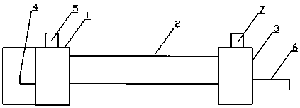
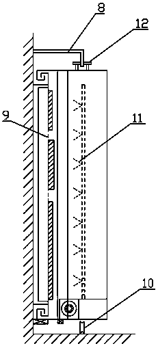
[0015] Such as figure 1 , 2 As shown, the material drying device includes a feed box 1, a drying box 2, and a discharge box 3. The top of the feed box 1 is provided with an air inlet, and the side of the feed box 1 is integrally provided with a feed port 4 , be provided with hot air blower 5 at air inlet; A slide rail 8 is provided between the feed box 1 and the drying box 2, between the drying box 2 and the discharge box 3, and a material placement platform 9 is provided on the slide rail 8 between the feed box 1 and the drying box 2 , the bottom of the material placement platform 9 is fixed with casters 10 and the casters 10 reciprocally slide o...


PUM


Abstract

The invention relates to the technical field of belt conveying devices, in particular to a material drying device, which includes a feed box, a drying box, and a discharge box. The top of the feed box is provided with an air inlet, which is integrally A material inlet is provided, and a hot air blower is arranged at the air inlet; an air outlet is arranged on the top of the discharge box, and a discharge outlet is integrally provided on the side of the discharge box, and an induced draft fan is arranged at the air outlet. Slide rails are provided between the feed box and the drying box, between the drying box and the discharge box, and a material placement table is provided on the slide rail between the feed box and the drying box, and the bottom of the material placement table is fixed There are casters and the casters reciprocally slide on the slide rails in the drying box; the lower part of the material placement table is fixed with a controller for controlling the movement of the material placement table and a motor for controlling the rotation speed of the casters, and the motor is electrically connected to the controller . The drying speed of the invention is fast and the efficiency is high. The wood dried by the method is uniform, not deformed and not cracked.

Description

technical field [0001] The invention relates to the technical field of wood product drying, in particular to a material drying device. Background technique [0002] In the production of wooden doors, the purpose of drying wood is to ensure the quality of the door and prolong the service life. Appropriate measures must be taken to reduce the moisture (moisture content) in the wood to a certain extent. In the drying process, there are currently two commonly used microwave drying methods for wood: one is the tunnel type, that is, the wood to be dried is placed on the conveyor belt, and the microwave generating device is installed above the conveyor belt; the other is the kiln type, which is about to be dried. The dry wood is placed in a closed space, and the microwave generating device is arranged somewhere in the enclosure structure of the space. Among them, although the continuous and automatic production efficiency of tunnel microwave drying is relatively high, it has relat...

Claims


Application Information

Patent Timeline
Patent Type & Authority Applications(China)
IPC IPC(8): F26B15/00F26B21/00F26B3/347F26B25/00
CPCF26B15/00F26B3/347F26B21/001F26B25/00F26B2210/16
Inventor 吴丹
Owner 湖州南浔丽学木制品厂
Why Eureka
Try Eureka