Forced caving hydraulic support

A hydraulic support and steering hydraulic technology, which is applied to mine roof supports, support devices, drilling equipment, etc., can solve problems such as narrow working space for workers, low labor productivity on working faces, and workers unable to work.

Inactive Publication Date: 2018-03-30
XUZHOU UNIV OF TECH
View PDF0 Cites 5 Cited by
  • Summary
  • Abstract
  • Description
  • Claims
  • Application Information

AI Technical Summary

Problems solved by technology

[0004] In the above method, if the drilling is carried out at the roadway position at the end of the working face, it is necessary to drill a deeper hole obliquely to the goaf direction so that the position of the hole can reach the top of the goaf, and the workload is relatively large; The roadway at the end of the working face is an advanced stress area, which requires advanced support, that is, generally more single pillars are required for support, and the single support and coal transportation equipment occupy a lot of space, causing workers to work hard. small space
And if the hole is drilled at the working face, because the working face is now mostly supported by hydraulic supports instead of single pillars, the top beam of the hydraulic support completely covers the roof, and workers cannot work; while if traditional single pillars are used for support , since the top beam of the single pillar can only cover part of the roof, workers can drill holes on the roof, but the effect of the single pillar supporting the roof is poor, and the labor production efficiency of the working face is low. The risk factor is higher during the hole process

Method used


Image

  • Forced caving hydraulic support
  • Forced caving hydraulic support
  • Forced caving hydraulic support

Examples


Embodiment Construction

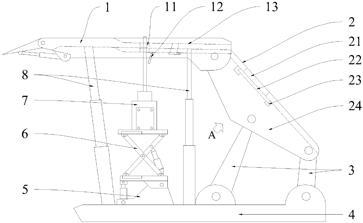
[0037] The present invention will be described in further detail below in conjunction with accompanying drawing, wherein in the description process, with figure 1 The left side is the front, figure 1 The right side of is the rear, perpendicular to figure 1 The paper faces out to the left, perpendicular to figure 1 Paper faces inwards to the right.

[0038] Such as figure 1 As shown, a forced caving hydraulic support includes a base 4, a column 8, a top beam 1, a cover beam 2, and a connecting rod 3. There are at least two columns 8 side by side, the lower end of which is fixed on the base 4, and the upper end is fixed on the The roof beam 1 is supported on the top beam 1, and there are side guard plates 24 on both sides of the shield beam 2. The other end is hingedly connected with the base 4; the base 4 is provided with a steering mechanism 5, a lifting mechanism 6 and a drilling mechanism 7;

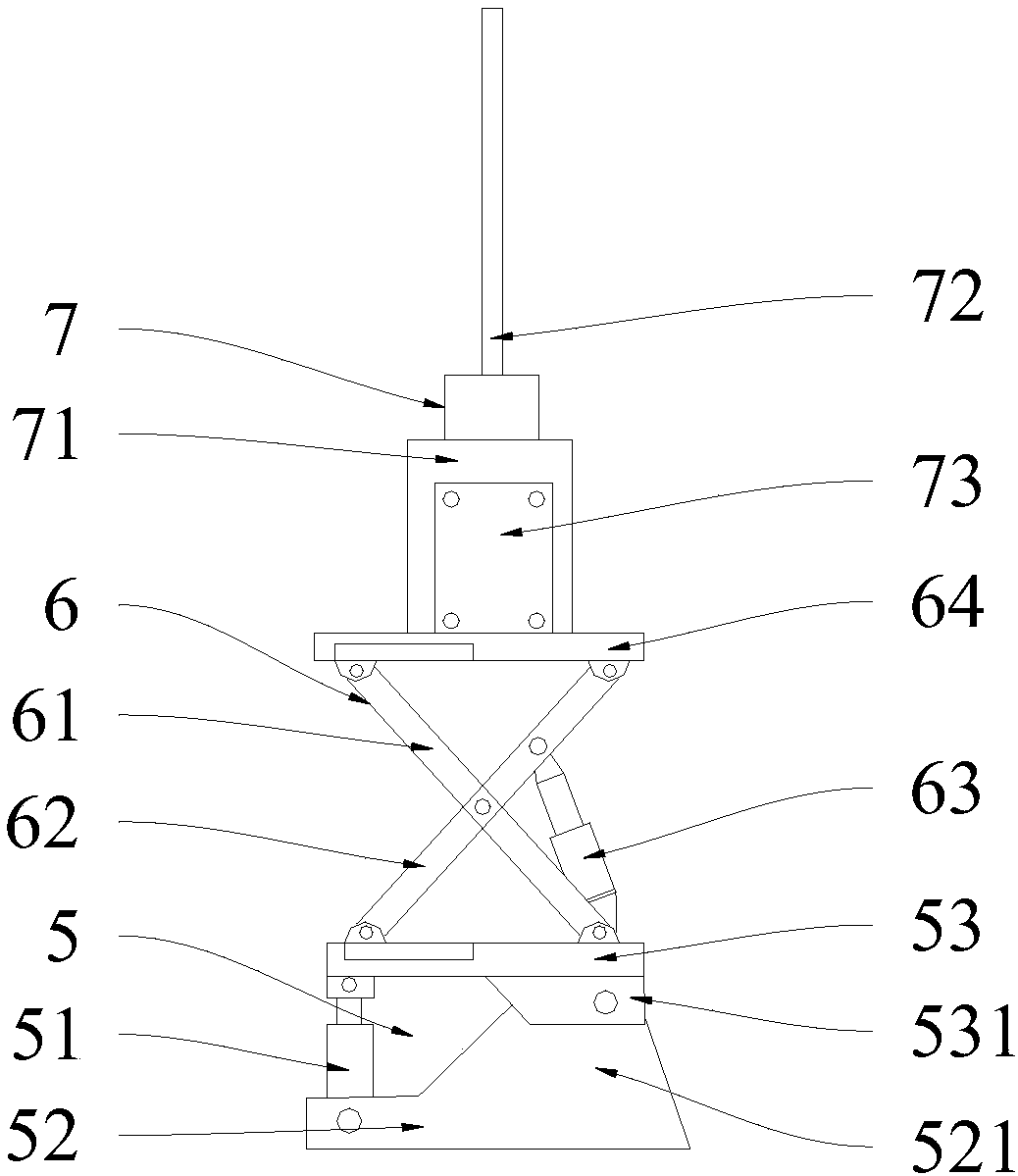
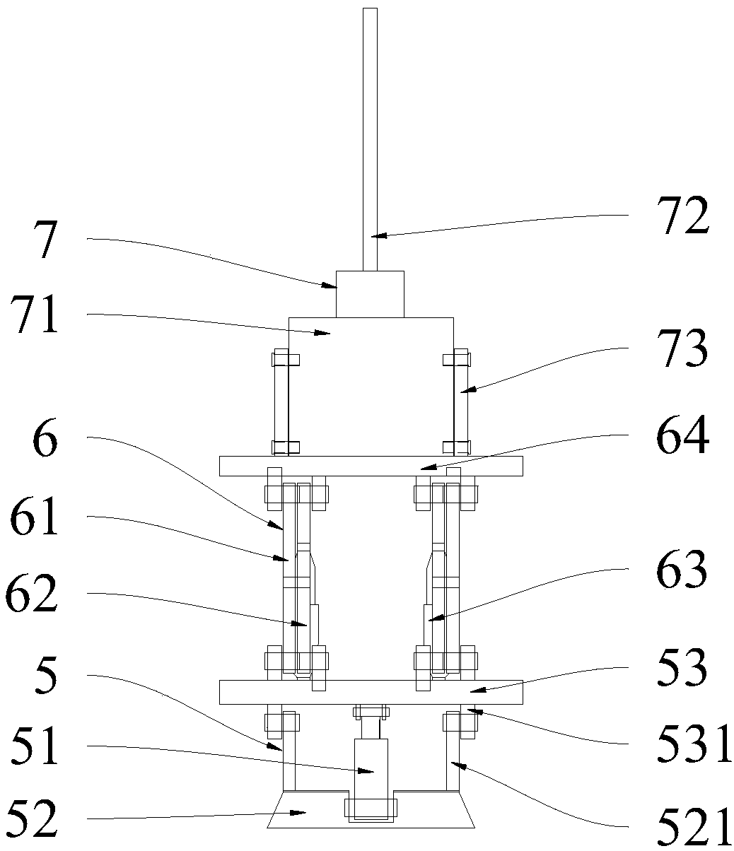
[0039] Such as figure 2 and image 3 As shown, the steering mechanism 5 in...


PUM


Abstract

The invention discloses a forced caving hydraulic support. A steering mechanism (5), a lifting mechanism (6) and a drilling mechanism (7) are arranged on a base (4) on the hydraulic support, the lifting mechanism (6) is located on the steering mechanism (5), the drilling mechanism (7) is movably mounted on the lifting mechanism (6), and a through hole (11) is formed in the position, correspondingto a drilling rod (72) in the drilling mechanism (7), of a top beam (1). Meanwhile, a groove (13) which extends in the front-back direction is formed in the upper surface of the top beam (1), the through hole (11) is located in the groove (13), and the rear end of the groove (13) extends to the rear end of the top beam (1). In use, the lifting mechanism (6) and the drilling mechanism (7) are matched to drill a top plate, then explosives are filled, thus the top plate at a drill hole (101) can be exploded, and forced caving is achieved accordingly. According to the forced caving hydraulic support, the work amount of workers is reduced, operation safety is ensured, and the supporting effect of a coal face is not affected.

Description

technical field [0001] The invention relates to a hydraulic support, in particular to a forced caving hydraulic support, which belongs to the field of coal mining machinery. Background technique [0002] In the process of underground coal mining, as the coal mining face advances, a goaf is formed behind it. Generally, the roof above the goaf continuously collapses under the action of gravity; but when the thickness of the roof above the coal seam is large Or when it is relatively hard, there will be a phenomenon that the roof is difficult to collapse by its own weight, and the overhang area of ​​the roof will continue to increase as the working face advances forward. Once the force on the roof reaches its ultimate strength, it will cause a large area of ​​the roof to collapse at the same time. The instantaneous pressure on the roof of the working face increases suddenly, crushing the mining support equipment of the working face, destroying the working face and the surroundin...

Claims


Application Information

Patent Timeline
IPC IPC(8): E21D23/00E21D23/04E21D23/03E21B15/00
CPCE21D23/0034E21B15/00E21D23/03E21D23/04
Inventor 唐珊陈亮王磊赵恩兰董妍张磊陈昊
Owner XUZHOU UNIV OF TECH
Why Eureka
Try Eureka