Blank discharging device for large-section vertical continuous casting machine

A billet ejecting device and continuous casting machine technology, which is applied in the field of slab ejecting devices for large-section vertical continuous casting machines, can solve the problems of unfavorable overall quality of casting billets, low work efficiency, and large space occupied, and can reduce the height of the workshop, Space saving, easy maintenance effect

Pending Publication Date: 2018-03-30
MCC CAPITAL ENGINEERING & RESEARCH
View PDF10 Cites 1 Cited by
  • Summary
  • Abstract
  • Description
  • Claims
  • Application Information

AI Technical Summary

Problems solved by technology

This kind of operation needs to set up cranes and other devices separately, the facilities occupy a large area, take up a lot of space, and the work efficiency is low, which is not conducive to the overall quality of the billet

Method used


Image

  • Blank discharging device for large-section vertical continuous casting machine
  • Blank discharging device for large-section vertical continuous casting machine
  • Blank discharging device for large-section vertical continuous casting machine

Examples


Embodiment Construction

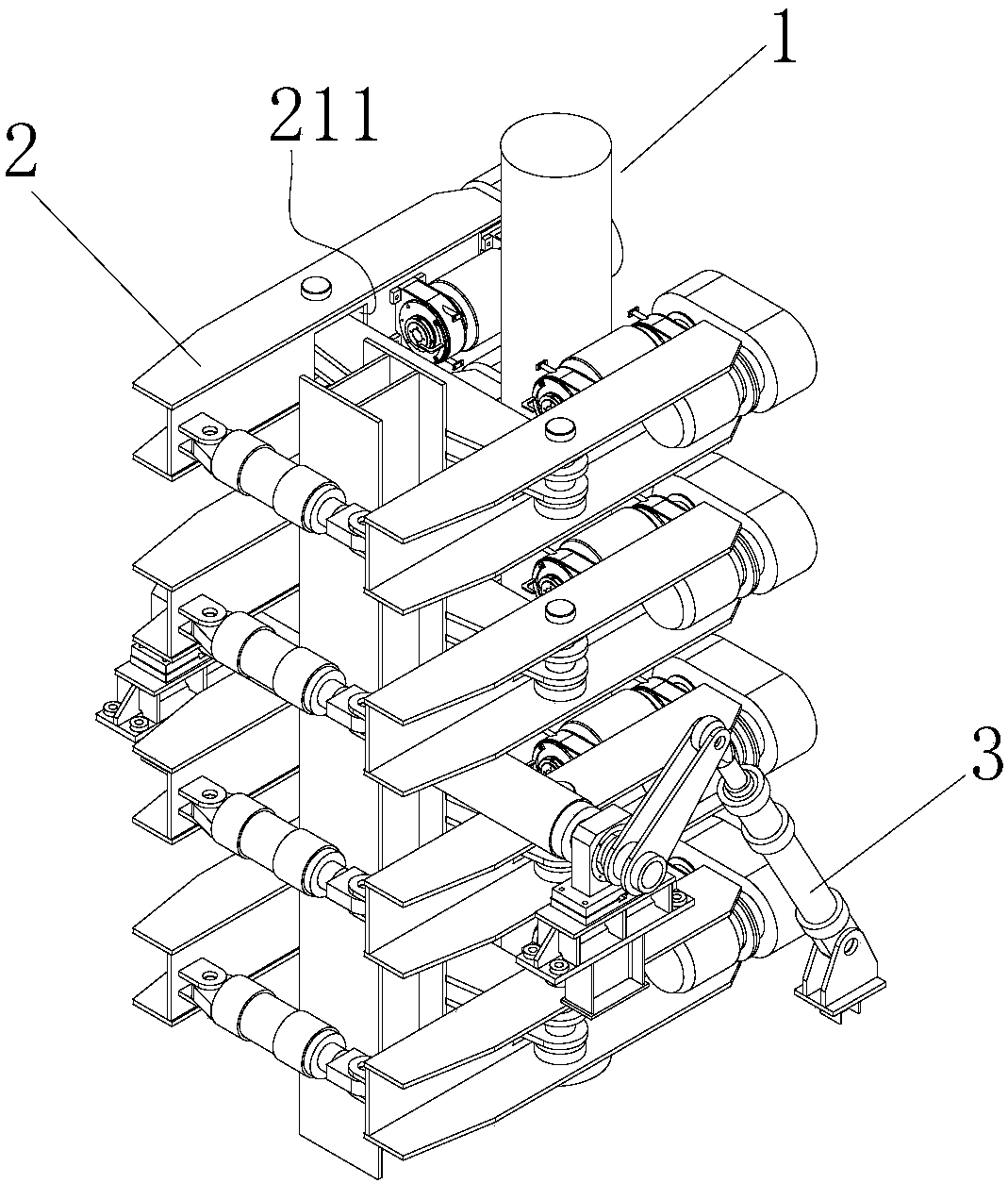
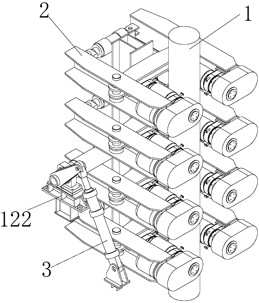
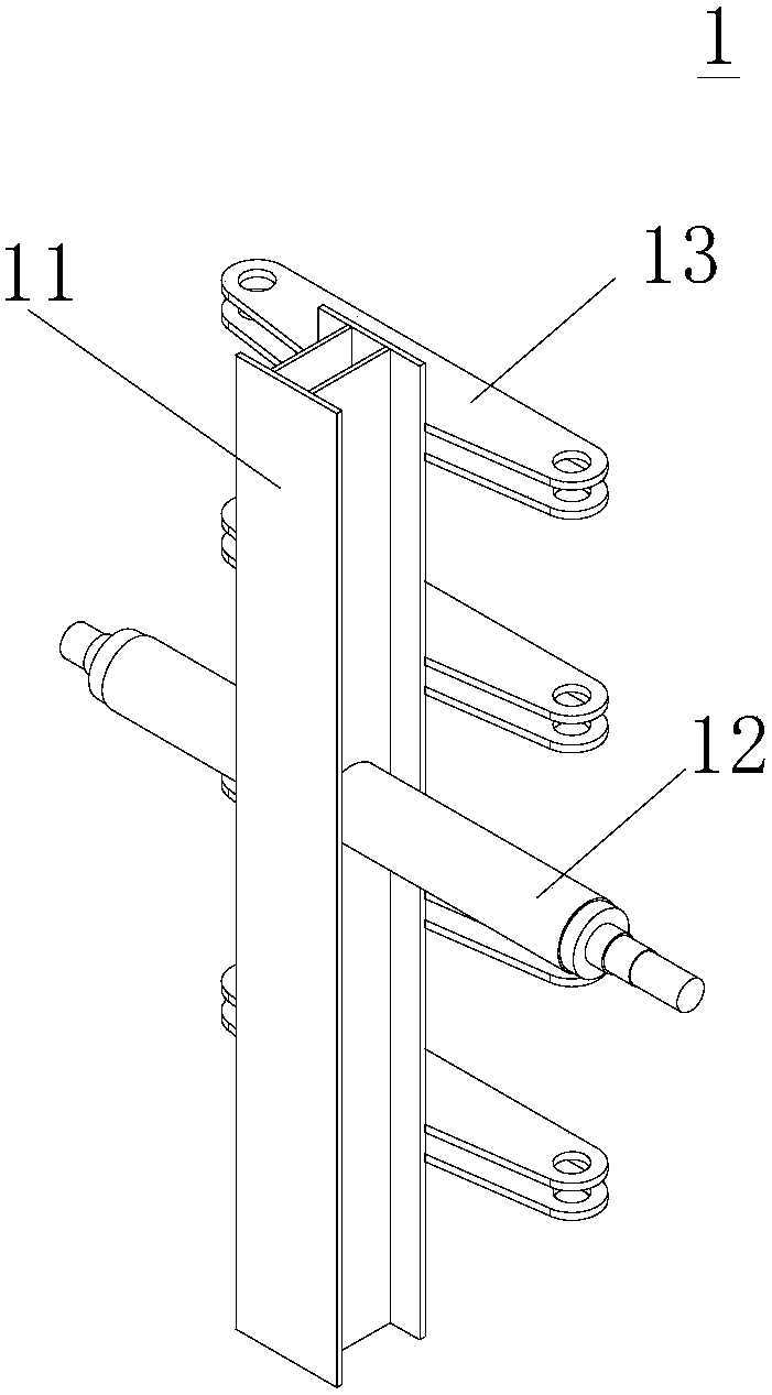
[0029] The present invention proposes a billet discharge device for a large-section vertical continuous casting machine, which includes: a supporting frame, which is provided with a column and a synchronous shaft, the synchronous shaft is horizontally arranged, and is fixed on the column; A plurality of clamping mechanisms are vertically spaced on the column. The clamping mechanism includes two parallel connecting rods. A driving roller is respectively installed at the front ends of the two connecting rods, and a driving roller is connected between the rear ends of the two connecting rods. Clamping the hydraulic cylinder, there is a bracket pivotally connected between the two, the bracket is parallel to the synchronous shaft, it is installed on the column, and the two driving rollers are set opposite to each other, and a gap is formed between the two for placing In the accommodating space of the slab, the axial direction of the drive roller is in the same direction as the lengt...


PUM


Abstract

The invention provides a blank discharging device for a large-section vertical continuous casting machine. The blank discharging device comprises a supporting frame, a plurality of clamping mechanismsand a rotary mechanism; the supporting frame is provided with a stand column and a synchronous shaft, and the synchronous shaft is horizontally arranged and fixedly arranged on the stand column in apenetrating manner; the plurality of clamping mechanisms are vertically arranged on the stand column in a spaced mode, each clamping mechanism comprises two parallel connecting rods, the front ends oftwo parallel connecting rods of each clamping mechanism are provided with driving rollers respectively, and a clamping hydraulic cylinder is connected between the two rear ends of two parallel connecting rods of each clamping mechanism; a support is pivoted between two parallel connecting rods of each clamping mechanism, the supports are parallel to the synchronous shaft and are arranged on the stand column, two driving rollers of two parallel connecting rods of each clamping mechanism are arranged oppositely, and a containing space is formed between two driving rollers of two parallel connecting rods of each clamping mechanism; the axial direction of each driving roller is in the same direction as the length direction of each connecting rod, and the axial direction of each driving rolleris perpendicular to the length direction of the synchronous shaft; and the rotary mechanism comprises a rotary drive hydraulic cylinder and a swing arm, one end of the swing arm is fixedly connectedto one end of the synchronous shaft in a sleeving mode, and the other end of the swing arm is connected with the rotary drive hydraulic cylinder. The blank discharging device is compact in structure,capable of saving space, capable of accurately and stably turning a casting blank and capable of smoothly completing blank discharging work of the casting blank.

Description

technical field [0001] The invention relates to a billet discharging device in a continuous casting machine in a steel plant, in particular to a billet discharging device for a vertical continuous casting machine with a large section. Background technique [0002] At present, domestic continuous casting machines are mostly arc continuous casting machines. When the casting billet passes through the straightening machine, the casting billet is straightened, and after cutting, it is directly off the assembly line with a crane, or it enters the cooling bed and then goes off the assembly line with a crane, and the casting billet is transported. onto the horizontal roller table. This type of operation requires separate installation of cranes and other devices. The facility occupies a large area and takes up a lot of space, and the work efficiency is low, which is not conducive to the overall quality of the billet. [0003] In view of this, the present inventor has developed a bil...

Claims


Application Information

Patent Timeline
Patent Type & Authority Applications(China)
IPC IPC(8): B22D11/128B22D11/041
CPCB22D11/041B22D11/128
Inventor 周善红张帅代宗岭陈卫强韩柏金韩长仪
Owner MCC CAPITAL ENGINEERING & RESEARCH
Why Eureka
Try Eureka