Low voltage electric equipment cabinet
A technology for low-voltage electrical and equipment cabinets, which is applied in substation/power distribution device shells, etc., which can solve problems such as increased production costs, doors that cannot be closed, and cabinets that are invalid, and achieve cost savings, avoid cabinet invalidation, and efficient operation.
- Summary
- Abstract
- Description
- Claims
- Application Information
AI Technical Summary
Problems solved by technology
Method used
Image

Examples
Embodiment 1
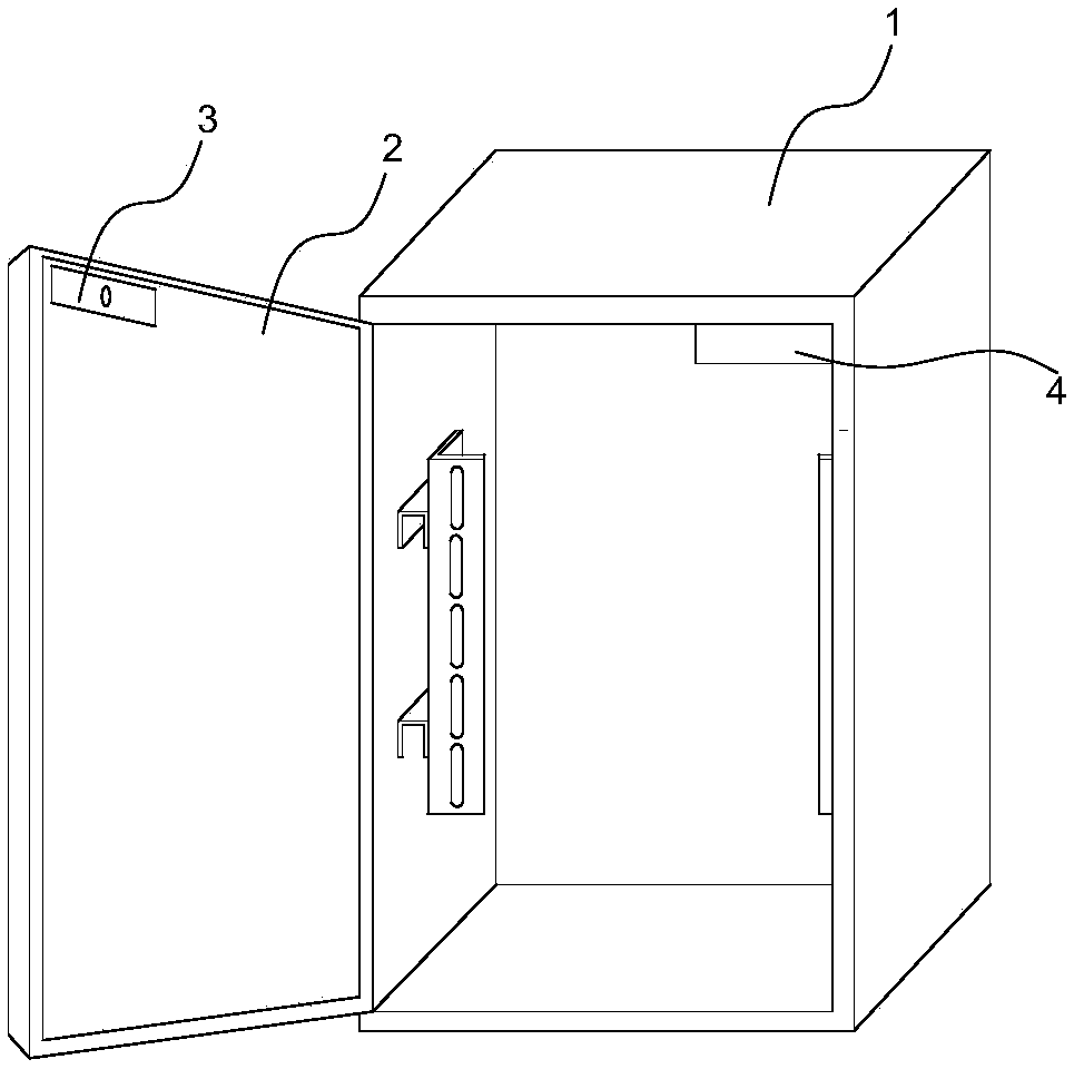
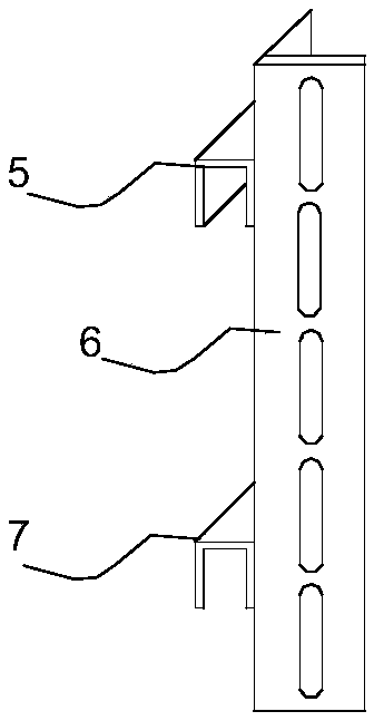
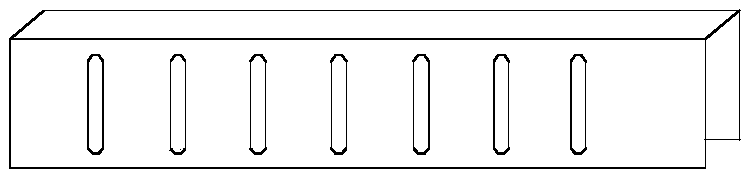
[0024] Such as figure 1 , figure 2 , image 3 As shown, this embodiment provides a low-voltage electrical equipment cabinet, including a cabinet body 1 and a door body 2, and an upper horizontal connecting frame 5 and a lower horizontal connecting frame 7 are welded to the inner side walls of the cabinet body 1, so that The lower transverse connecting frame 7 is welded below the upper transverse connecting frame 5, and the upper transverse connecting frame 5 and the lower transverse connecting frame 7 are U-shaped frame structures, and a plurality of first fixing holes are arranged at intervals on the outer sides thereof, and are longitudinally connected The frame 6 is an angle steel, and its two walls are provided with a plurality of second fixing holes, and the second fixing holes on one wall of the longitudinal connecting frame 6 are connected with the first fixing holes by bolts.
[0025] According to the technical solution provided by the embodiment of the present app...
Embodiment 2
[0027] Such as figure 1 , Figure 4 As shown, this embodiment is based on Embodiment 1, and a suction block 3 is arranged on the door body 2, and an electromagnetic block 4 is arranged at a corresponding position on the cabinet body 1, and the suction block 3 is in phase with the electromagnetic block 4. Used together, when the power is turned on, the electromagnetic block 4 generates magnetic force to attract the suction block 3, so that the door body 2 cannot be opened.
[0028] Wherein, the electromagnetic block 4 adopts a silicon steel sheet, which is welded into a W shape, and a copper core coil 8 is wound on the electromagnetic block 4 .
[0029] Wherein, the suction block 3 is an iron block.
[0030] According to the technical solution provided by the embodiment of the present application, the electromagnetic block 4 is installed on the cabinet body 1, and the suction plate is installed on the door. When electrified, the electric lock has no current passing through,...
Embodiment 3
[0032] Such as figure 1 , Figure 5 As shown, the present embodiment is improved on the basis of Embodiment 2. The door body 2 is a detachable door body 2, and the door body 2 is provided with an elastic insertion rod 12 structure, through which the elastic insertion rod The 12 structure is connected with the cabinet body 1, the elastic insertion rod 12 structure includes an upper clamping block 9, a spring 10, a fixed block with holes 11, and an insertion rod 12, and the fixed block 11 with holes is welded on the door body 2, and the An upper clamping block 9 is welded on the inserting rod 12, a spring 10 is sleeved on the inserting rod 12 between the upper clamping block 9 and the fixed block 11 with holes, and the lower end of the inserting rod 12 passes through the fixed block with holes 11. The upper end of the insertion rod 12 passes through the edge of the door body 2 .
[0033] Wherein, an insertion hole is provided on the cabinet body 1 at a position corresponding ...
PUM
 Abstract
Description
Claims
Application Information
 - Generate Ideas
- Intellectual Property
- Life Sciences
- Materials
- Tech Scout
- Unparalleled Data Quality
- Higher Quality Content
- 60% Fewer Hallucinations
Browse by: Latest US Patents, China's latest patents, Technical Efficacy Thesaurus, Application Domain, Technology Topic, Popular Technical Reports.
© 2025 PatSnap. All rights reserved.Legal|Privacy policy|Modern Slavery Act Transparency Statement|Sitemap|About US| Contact US: help@patsnap.com