Universal micro switch with forced separation
A micro switch, a general-purpose technology, applied in the direction of electric switches, electrical components, circuits, etc., can solve the problems of increasing the burden of elastic parts, attenuation of switch elastic force, and failure of switch action, so as to prevent detachment or chip loss and improve reset. ability, the effect of preventing material deformation
- Summary
- Abstract
- Description
- Claims
- Application Information
AI Technical Summary
Problems solved by technology
Method used
Image
Examples
Embodiment 1
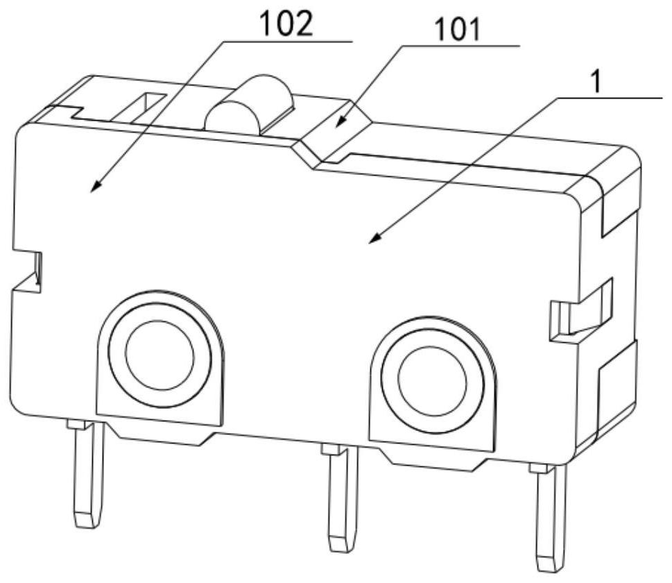
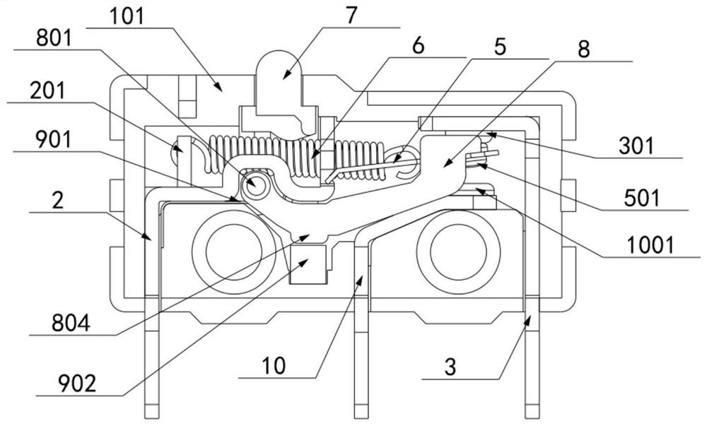
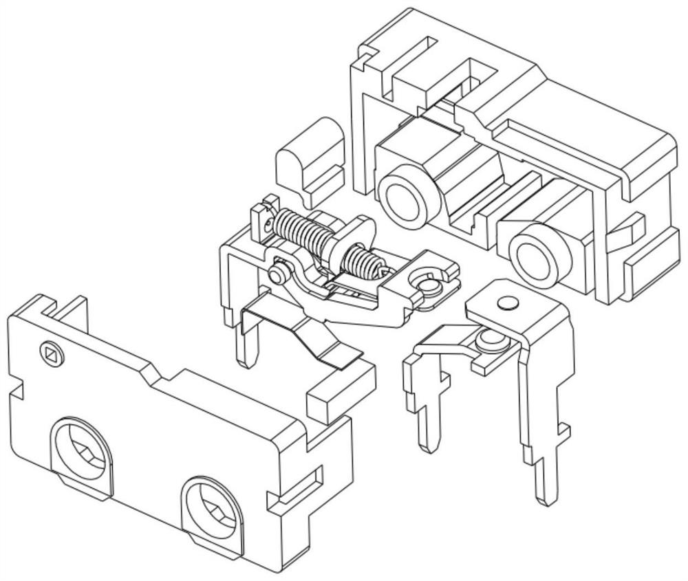
[0051] Such as figure 1 , figure 2 and image 3 A general-purpose microswitch with forced separation shown includes a housing 1 composed of a bottom case 101 and an upper cover 102, as shown in figure 2 As shown, the housing is provided with a common terminal connector 2, a normally closed connector 3, a normally open connector 10, a movable contact piece 5, an elastic member 6, and a button 7. The button 7 is linked to the elastic member 6, and under the action of the button 7 The elastic part 6 drives the movable contact piece 5 to swing to switch from normally closed to normally open to realize switching on and off; a forced separation part 8 is also provided in the housing 1, one end of which is installed on the housing 1 through a rotating shaft 801, and the other One end rests on the moving contact piece 5, and the middle part extends the first support part 803 below the elastic member 6. The first support part is specifically a protrusion, which is forced to separat...
Embodiment 2
[0058] Embodiment 2 is basically the same as Embodiment 1, the difference is:
[0059] Such as Figure 17 and Figure 18 As shown, the elastic member 6 is a reed, one end of the reed abuts against the common terminal connector 2, and the other end of the reed abuts against the movable contact piece 5; wherein the movable contact piece 5 has elasticity and can be bent and deformed; One end of the contact piece 5 abuts against the groove 203 at the left end of the public connector 2, and the other end is provided with a movable contact 501 and is in contact with the normally closed connector 3; On the contact piece 5 and impel the moving contact piece to bend and deform. Such as Figure 22 and Figure 23 The forced separation 8 is shown.
[0060] Such as Figure 17 As shown, there is a cavity between the two rotating shafts 801 of the forced separation member 8 that can accommodate the elastic reed and the swing of the movable contact piece 5, and the first support portion...
Embodiment 3
[0066] Embodiment 3 is basically the same as Embodiment 2, the difference is:
[0067] Such as Figure 20 and Figure 21 As shown, the elastic member 6 is a reed, and the reed and the movable contact piece 5 are integrally arranged. Other positions and connections are the same as in Embodiment 2.
[0068] Working principle: the same as embodiment 2.
PUM
 Abstract
Description
Claims
Application Information
 - R&D
- Intellectual Property
- Life Sciences
- Materials
- Tech Scout
- Unparalleled Data Quality
- Higher Quality Content
- 60% Fewer Hallucinations
Browse by: Latest US Patents, China's latest patents, Technical Efficacy Thesaurus, Application Domain, Technology Topic, Popular Technical Reports.
© 2025 PatSnap. All rights reserved.Legal|Privacy policy|Modern Slavery Act Transparency Statement|Sitemap|About US| Contact US: help@patsnap.com


