Spindle rails for ring spinning machines

A ring spinning machine, spindle rail technology, used in spinning machines, continuous winding spinning machines, textiles and papermaking, etc., to achieve high yarn yields

Inactive Publication Date: 2020-05-29
ROTORCRAFT SA (PTY) LTD
View PDF2 Cites 0 Cited by
  • Summary
  • Abstract
  • Description
  • Claims
  • Application Information

AI Technical Summary

Problems solved by technology

The result is a series of advantages

Method used


Image

  • Spindle rails for ring spinning machines
  • Spindle rails for ring spinning machines

Examples


Embodiment Construction

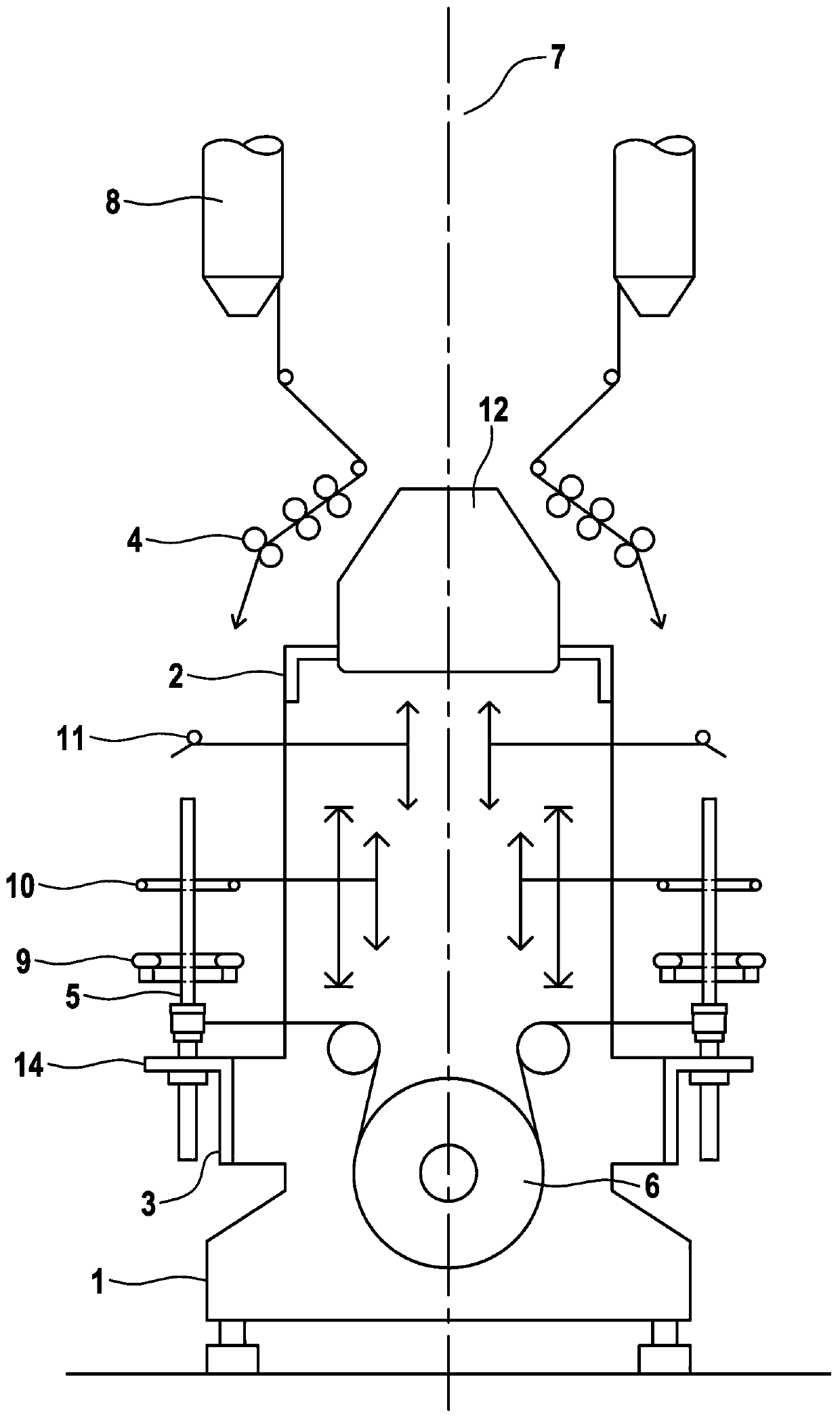
[0043] in figure 1 An example of a ring spinning machine with a unified structure that has been widely used and provided so far is shown in. The stable intermediate support 1 arranged transversely to the longitudinal axis of the ring spinning machine is equipped with longitudinal beams 2 and 3 for accommodating the drafting device 4 and the spindle 5. Between the drafting devices there is an air channel 12 for sucking away the broken yarn. Between the spindles 5 are a spindle drive mechanism 6 fixedly arranged on the machine and a fixed-position spindle rail 14, and above the drafting device is a creel 7 with a roving bobbin 8. The longitudinal beams for the spinning ring 9, the balloon ring 10 and the yarn guide 11 whose movement space is indicated only by the vertical double arrow are vertically movable.

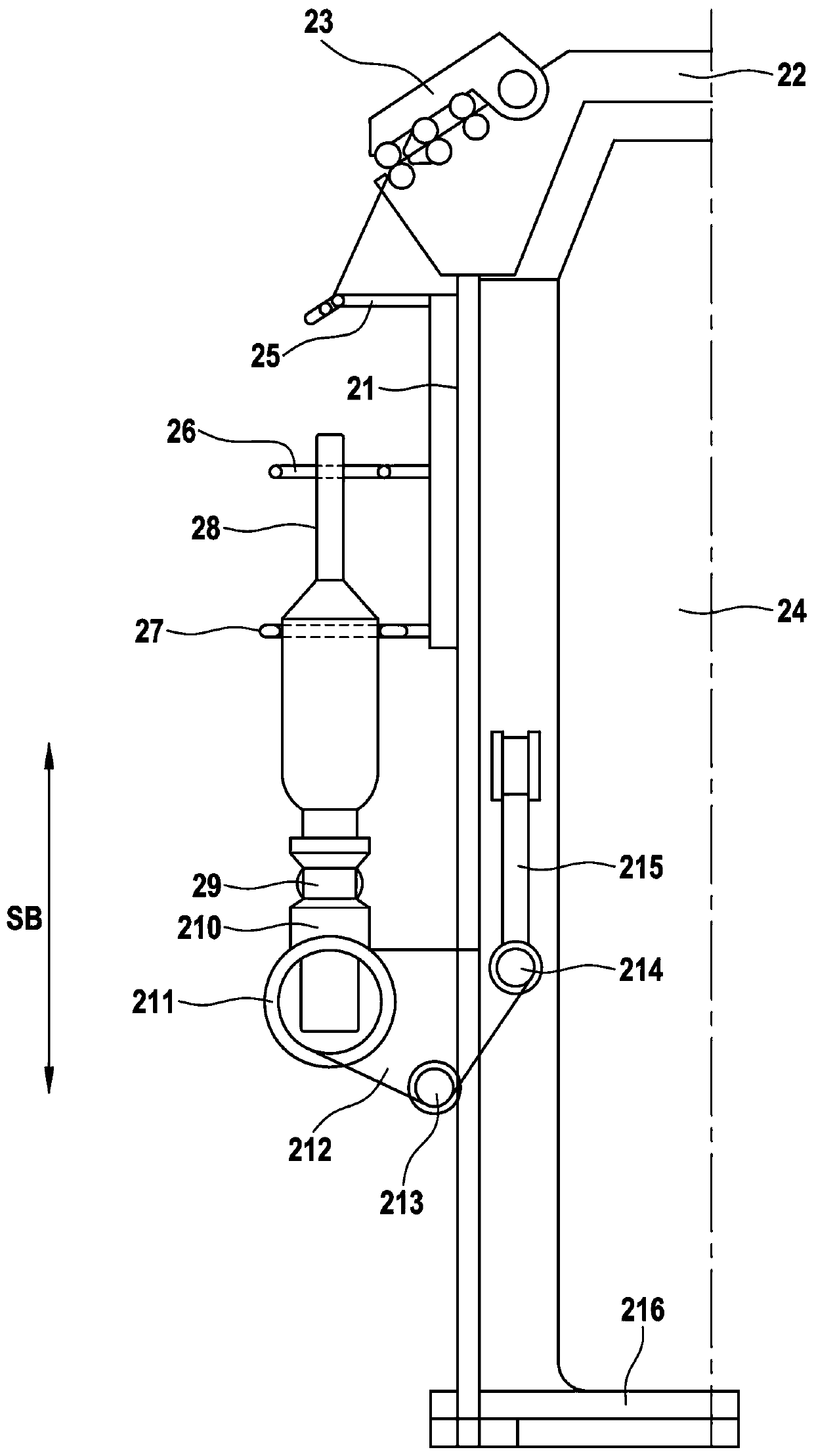
[0044] figure 2 Shows the left half of the ring spinning machine. One must understand that the centerline shown is a symmetrical whole machine. The yarn guide (pigtail y...


PUM


Abstract

The present application relates to a spindle rail for a ring spinning machine, which spindle rail is arranged on the frame of the ring spinning machine, characterized in that said spindle rail is arranged movable relative to said frame (21) And has assigned to it a drive mechanism (215) adapted to the execution of the vertical movement of the spindle rail (211) relative to the frame (21).

Description

Technical field [0001] The invention relates to a spindle rail for a ring spinning machine, which is arranged on a frame of the ring spinning machine. Background technique [0002] One of the weaknesses of today's ring spinning machines is that the yarn tension that limits the spinning speed encounters significant fluctuations when producing full bobbins. This involves a fixed height position of the spindle carried by the spindle rail and thus the bobbin in today's ring spinning machines, and the distance between the fiber leaving the drafting device and the yarn falling onto the yarn bobbin varies widely. The spindle speed is low at the beginning of the formation, then slowly increases to the highest value, and at the end it decreases significantly. The so-called "spindle speed" always exists at the maximum value in the middle section of the formation. The "medium" spindle speed important for yarn manufacturing is significantly lower. [0003] At this time, the position of the ...

Claims


Application Information

Patent Timeline
Patent Type & Authority Patents(China)
IPC IPC(8): D01H7/14D01H1/24
CPCD01H1/24D01H7/14D01H7/10D01H7/20D01H1/02
Inventor 汉斯·沙赫勒克尔
Owner ROTORCRAFT SA (PTY) LTD
Why Eureka
Try Eureka