
Matching structure of rim outer frame and tire

A technology of matching structure and outer frame, applied in tire parts, tire rims, rims, etc., can solve problems such as broken rope joints, fixed rope stress concentration, and bead 11' split.

Pending Publication Date: 2018-03-23
XIAMEN LENCO
View PDF6 Cites 0 Cited by
  • Summary
  • Abstract
  • Description
  • Claims
  • Application Information

AI Technical Summary

Problems solved by technology

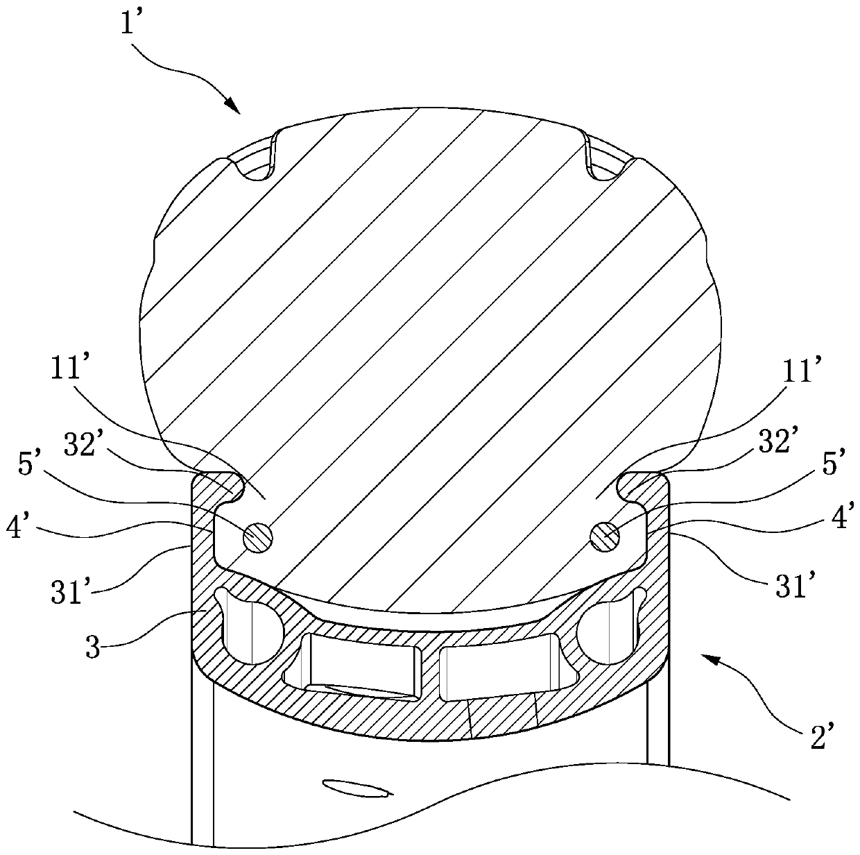
However, if the wheel is set in this way, under long-term use or under the action of high pressure, the fixed rope will cause stress concentration inside the tire 1', which will easily cause the bead portion 11' of the tire 1' to be split.
The rope is a manual operation. Due to the existence of pre-tightening force, the rope joint may break

Method used


Image

  • Matching structure of rim outer frame and tire
  • Matching structure of rim outer frame and tire
  • Matching structure of rim outer frame and tire

Examples


Embodiment 1

[0028] Such as Figure 5 As shown, the protruding portion 2 includes a first protruding portion 21 and a second protruding portion 22, the first protruding portion 21 and the second protruding portion 22 are distributed in a continuous ring around the inner wall of the rim outer frame 1, and The first protruding parts 21 and the second protruding parts 22 respectively located on the ring walls 11 on both sides are symmetrically distributed, and the first protruding parts 21 and the second protruding parts 22 are bent downward toward the inner direction of the rim to form an inverted The bead portion 31 of the tire 3 is provided with a groove 34 that cooperates with the protrusions 2 on the two sides of the ring wall 11, and the groove 34 is tightly fitted with the protrusion 2, thereby fixing the rim Box 1 and tire 3.

Embodiment 2

[0030] Such as Figure 6 As shown, the protruding portion 2a includes a first protruding portion 21a and a second protruding portion 22a, and the first protruding portion 21a and the second protruding portion 22a surround the inner wall of the rim outer frame 1 in a discontinuous annular distribution. There is at least one discontinuity 23a between the first protruding portion 21a and the second protruding portion 22a, and the first protruding portions 21a and the second protruding portions 22a respectively located on the ring walls 11 on both sides are symmetrically distributed. The first protruding portion 21a and the second protruding portion 22a are bent downward toward the inner direction of the rim to form an undercut. The mutually matched grooves 34a, said grooves 34a are closely fitted with the protrusions 2a, thereby fixing the rim outer frame 1 and the tire 3.

Embodiment 3

[0032] Such as Figure 7 As shown, the protruding portion 2b includes a first protruding portion 21b and a second protruding portion 22b, the first protruding portion 21b is distributed in a continuous ring around the inner wall of the rim outer frame 1, and the second protruding portion 22b Surrounding the inner wall of the rim outer frame 1 is a ring-shaped discontinuity 23b, the second protrusion 21b has at least one discontinuity 23b, and is respectively located on each first protrusion 21b and The second protrusions 22b are distributed symmetrically left and right respectively. The first protrusions 21b and the second protrusions 22b are bent downward toward the inside of the rim 1 to form an undercut. The bead portion 31 of the tire 3 is provided with The grooves 34 that cooperate with the protrusions 2 on the two side ring walls 11, the bead portion 31b of the tire 3b is provided with a groove 34b that cooperates with the protrusions 2b on the two side ring walls 11, th...


PUM


Abstract

The invention discloses a matching structure of a rim outer frame and a tire. The rim outer frame comprises two side annular walls and an outer frame bottom connected with the two side annular walls.The tire comprises a tread part, a tire side part and a tire lip part. The inner wall of each of the two side annular walls is provided with at least two protrusion parts continuously and annularly distributed around the inner wall of the corresponding side annular wall. Grooves matched with the protrusion parts on the two side annular walls are formed in the tire lip part of the tire. By the adoption of the matching structure, the traditional mode that a fixing rope is used for fastening the tire and the rim is abandoned, the structure that the protrusion parts are arranged on the inner wallsof the two side annular walls of the rim outer frame is adopted, the protrusion parts are embedded in the grooves of the tire lip part of the tire to achieve the fastening effect, through the arrangement, the situation that the fixing rope rubs against the tire and thus the tire lip part is split can be effectively prevented, the fastening effect between the tire and the rim is further guaranteed, and a tire falling phenomenon is effectively prevented.

Description

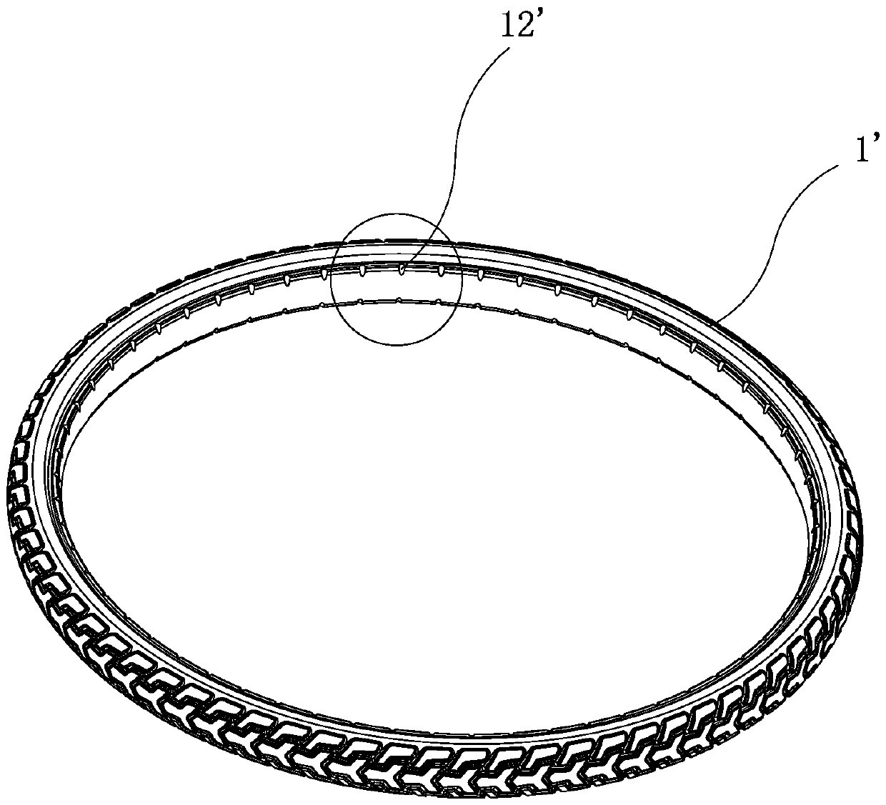
technical field [0001] The invention relates to a wheel structure, in particular to a matching structure between a wheel rim outer frame and a tire. Background technique [0002] Traditional wheels are usually composed of a rim and a tire, and the rim includes an outer frame and spokes. The outer frame is used to fix the tire. Due to the frequent use of the wheel, the tire is very easy to wear, and there is often a gap between the tire and the outer frame of the rim. Disengagement will occur. [0003] Such as figure 1 As shown, it is an existing connection structure between a tire 1' and a rim 2', wherein the outer frame 3' of the rim 2' includes two side ring walls 31', and the top of the two side ring walls is provided with a Inner protrusions 22', so that grooves 4' are formed on the ring walls 31' on both sides of the outer frame 3', by inserting the bead portion 11' of the tire 1' into the groove 4' of the outer frame 3' of the rim 2' The tire 1' is fixed, and then t...

Claims


Application Information

Patent Timeline
IPC IPC(8): B60B21/10B60C15/024
CPCB60B21/10B60C15/024
Inventor 龚毅
Owner XIAMEN LENCO
Learn More