
Front edge plate lifting device

A frontier board and pedal technology, applied in the field of elevators, can solve problems such as screw loss, screw hole wear, insufficient lifting force, etc., to achieve the effect of avoiding loss, improving reliability and safety, and improving reliability and safety

Inactive Publication Date: 2018-03-20
CANNY ELEVATOR
View PDF4 Cites 0 Cited by
  • Summary
  • Abstract
  • Description
  • Claims
  • Application Information

AI Technical Summary

Problems solved by technology

On the one hand, the screws at the reserved threaded holes will be lost after lifting. On the other hand, the threaded holes, as the structure of the bearing capacity, are frequently screwed in and out, and the wear is serious, which will lead to insufficient lifting force, slipping wires, etc.

Method used


Image

  • Front edge plate lifting device
  • Front edge plate lifting device

Examples


Embodiment Construction

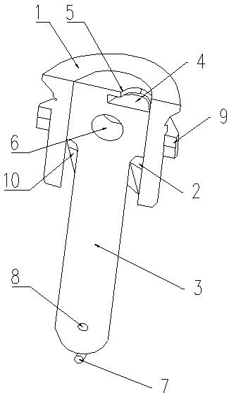
[0013] A leading edge plate lifting device related to the present invention has a pedal bushing 1, a chute 2 and a handle 3 arranged concentrically, wherein the chute 2 is set in the pedal bushing 1, and the handle 3 is connected in the chute 2. The chute 2 is also provided with an installation clamp 10 for limiting the handle 3, the diameter of the handle 3 on the upper side of the limit clamp 10 is greater than the diameter of the handle 3 on the lower side of the limit clamp 10, and the handle 3 The top of the top is provided with a lifting hole 4 and a lifting edge 2 arranged on the inner side of the lifting hole 4, and a lifting hole 6 passing through the handle 3 is provided under the lifting hole 4. The circlip mounting hole 8 of the circlip 7 is installed, and an external thread 11 is arranged on the outside of the pedal casing 1 , and a mounting nut 9 is sleeved on the external thread 11 .

[0014] In the specific use process, by inserting a tool such as a zipper into...


PUM


Abstract

The invention relates to a front edge plate lifting device and relates to the technical field of elevators. The front edge plate lifting device is provided with a pedal sleeve. A sliding groove is formed in the inner side of the pedal sleeve. A handle is connected into the sliding groove in a penetrating mode. The top of the handle is provided with a pulling hole and a pulling edge. A pulling holepenetrating through the handle is formed below the pulling hole. The bottom of the handle is provided with a snap ring and a snap ring mounting hole used for mounting the snap ring. An external thread is arranged on the outer side of the pedal sleeve. A mounting nut is connected with the external thread in a sleeving mode. A limiting clamping plate used for limiting the position of the handle isarranged in the sliding groove. The front edge plate lifting device has the beneficial effects that through cooperation and application of tools such as the handle and a head-shaped screwdriver, sufficient lifting force can be effectively ensured, the phenomenon of part losing in the past is avoided, and the lifting reliability and safety are improved.

Description

technical field [0001] The invention relates to a front plate lifting device, which belongs to the technical field of elevators. Background technique [0002] The traditional front panel lifting device uses the front panel handle to unscrew the screw reserved on the front panel surface, screw the other threaded end into the threaded hole, and use the threaded connection to tighten the screw. Solid principles to improve. On the one hand, the screws at the reserved threaded holes will be lost after lifting. On the other hand, as the structure of the bearing capacity, the threaded holes are frequently screwed in and out and worn out, which will lead to insufficient lifting force and slipping. Contents of the invention [0003] The technical problem to be solved by the present invention is to provide a front panel lifting device which is convenient for lifting the front panel and can avoid loss of parts. [0004] Aiming at the above technical problems, the present invention ...

Claims


Application Information

Patent Timeline
Patent Type & Authority Applications(China)
IPC IPC(8): B66B7/00
CPCB66B7/00
Inventor 陈莹申德云孙佳良
Owner CANNY ELEVATOR
Learn More