Upright cap buckle type cable distribution box with electronic tag
A junction box with electronic technology, applied in the direction of light guide, optics, optical components, etc., can solve problems such as damage, paper labels are easy to fall off, and structural design is incomplete
- Summary
- Abstract
- Description
- Claims
- Application Information
AI Technical Summary
Problems solved by technology
Method used
Image
Examples
Embodiment 1
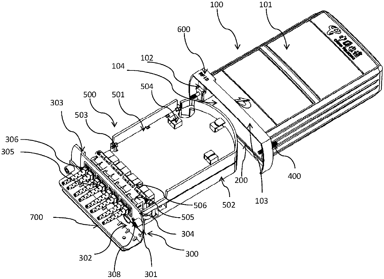
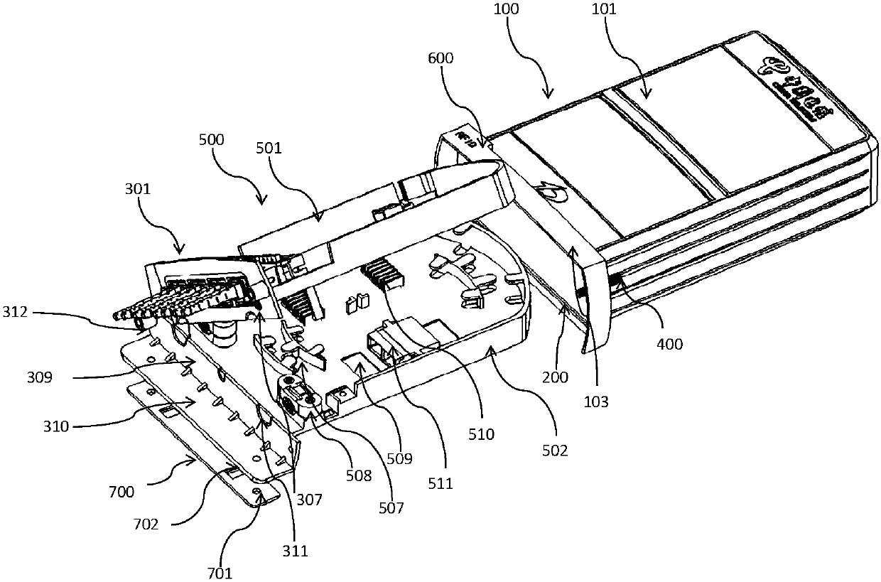
[0062] According to embodiments of the present invention, as Figure 1-2 As shown in the figure, an upright cap-buckle optical cable distribution box with an electronic label is proposed. The optical fiber-splitting box includes: a cap-buckle upper cover 100, a sealing ring 200, an end cover 300, a locking mechanism 400, and fiber fusion in the box. Optical fiber splitting assembly 500, electronic label 600 and fixing structure 700; wherein, the cap buckle type upper cover includes a box body 101, a mounting seat 102 and a mounting port 103; the box body 101 has a side length of a×b× c is a near-cuboid, and a>b>3c, wherein one surface of the near-cuboid whose side length is b×c is the lower surface, and the lower surface has an opening 104 structure; the remaining 5 surfaces are closed structures; in this implementation In Example 1, a=220mm, b=165mm, c=70mm; each edge of the nearly rectangular parallelepiped except the lower surface edge has arc excessive chamfering; and the ...
Embodiment 2
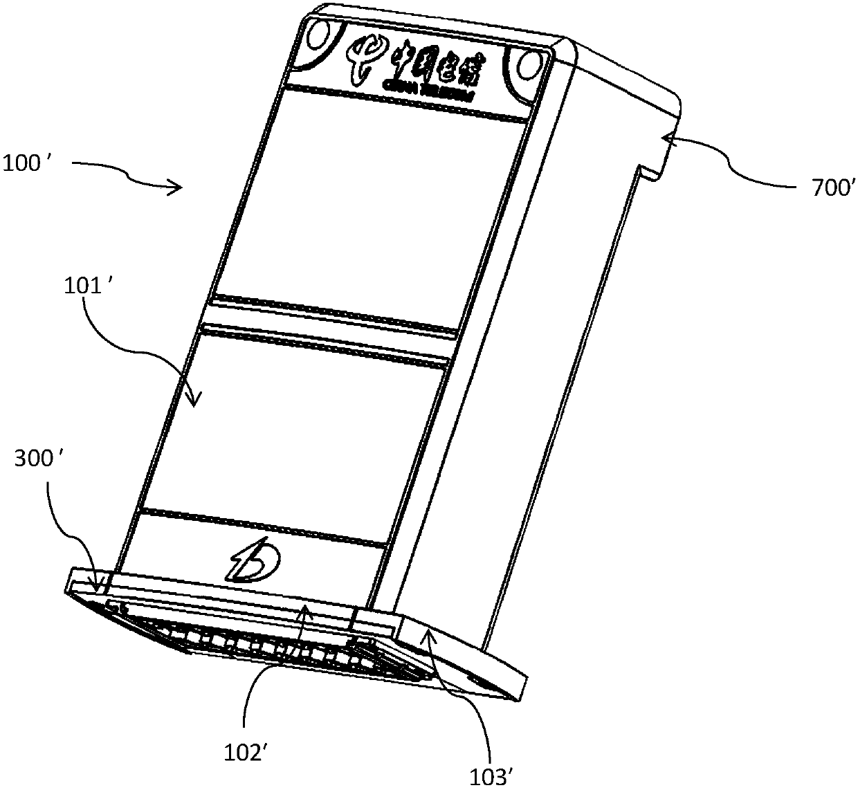
[0071] According to embodiments of the present invention, as Figure 3-6 As shown, an upright cap-buckle optical cable distribution box with an electronic label is proposed. The optical fiber-splitting box includes: a cap-buckle upper cover 100', a sealing ring 200' (not shown), an end cover 300', The locking mechanism 400', the fused fiber splitting fiber splitting assembly 500' in the box, the electronic label 600' (not shown) and the fixing structure 700'; wherein, the cap-type upper cover includes the box body 101' and the mounting seat 102' and the installation port 103 ′; the box body 101 ′ is a nearly cuboid whose side lengths are respectively a×b×c, and the a>b>3c, wherein one surface of the nearly cuboid whose side length is b×c is the bottom surface, the lower surface has an opening 104' structure (not shown); the remaining 5 surfaces are closed structures; in this embodiment 2, a=185mm, b=145mm, c=55mm; the lower surface of the nearly cuboid is removed Each edge ou...
Embodiment 3
[0080] The difference between this embodiment and Embodiment 1 is that a=160mm, b=130mm, c=40mm; the opening has the following structure: the opening is the entire lower surface; the mounting seat is formed by the edges of the opening The skirt is formed by extending vertically outward from each side of the cuboid, the projected shape of the skirt on the left and right sides has arc-shaped edges, the diameter of the arc is 140mm, and the projected shape of the skirt on the front side has a circular arc. Edge, the projected shape of the skirt on the rear side has a straight edge, and the maximum width of the front skirt is 4mm, and the width of the rear side is 2mm; the installation is perpendicular to the front and left and right sides of the skirt. The frame extending downward from the seat surrounds the installation opening; the lower edge of the frame is in a plane, and the plane is parallel to the lower surface, and the distance between the two is 5mm;
[0081]The end cove...
PUM
 Abstract
Description
Claims
Application Information
 - R&D Engineer
- R&D Manager
- IP Professional
- Industry Leading Data Capabilities
- Powerful AI technology
- Patent DNA Extraction
Browse by: Latest US Patents, China's latest patents, Technical Efficacy Thesaurus, Application Domain, Technology Topic, Popular Technical Reports.
© 2024 PatSnap. All rights reserved.Legal|Privacy policy|Modern Slavery Act Transparency Statement|Sitemap|About US| Contact US: help@patsnap.com


