
Heat pump main unit

A technology of heat pump main engine and heat pump device, which is applied in the direction of heat pump, refrigerator, lighting and heating equipment, etc. It can solve the problems of complex system installation, high cost, and inability to realize standardized installation, and achieve the effect of simplifying engineering installation and ensuring intelligent control

Inactive Publication Date: 2018-03-16
广州春光新能源科技发展有限公司
View PDF9 Cites 0 Cited by
  • Summary
  • Abstract
  • Description
  • Claims
  • Application Information

AI Technical Summary

Problems solved by technology

The heat pump system usually includes two parts: the outdoor heat pump host and the indoor terminal equipment; in the existing heat pump system, the outdoor heat pump host and the indoor terminal equipment each have a controller, and at the project installation site, it is necessary to accurately connect the control circuits of the two parts to realize the whole process. The operation of the heat pump system, the installation of the system is complicated, the standardized installation cannot be realized, and the cost is high

Method used


Image

  • Heat pump main unit
  • Heat pump main unit

Examples


Embodiment Construction

[0022] The following will clearly and completely describe the technical solutions in the embodiments of the present invention with reference to the accompanying drawings in the embodiments of the present invention. Obviously, the described embodiments are only some, not all, embodiments of the present invention. Based on the embodiments of the present invention, all other embodiments obtained by persons of ordinary skill in the art without making creative efforts belong to the protection scope of the present invention.

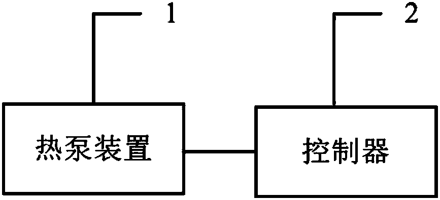
[0023] see figure 1 , is a structural schematic diagram of an embodiment of the heat pump host provided by the present invention.

[0024] An embodiment of the present invention provides a heat pump host, including: a heat pump device 1 and a controller 2;

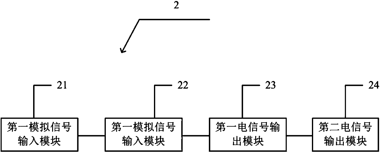
[0025] Please also refer to figure 2 , the controller 2 includes a first analog signal input module 21, a second analog signal input module 22, a first electrical signal output module 23 and a second el...


PUM


Abstract

The invention discloses a heat pump main unit. The heat pump main unit comprises a heat pump device and a controller, the controller comprises a first simulation signal input module, a second simulation signal input module, a first electric signal output module and a second electric signal output module. According to the heat pump main unit, the control function of a whole heat pump system is integrated into the controller of the heat pump main unit, intelligent control over the heat pump system is ensured, and engineering mounting is simplified.

Description

technical field [0001] The invention relates to the field of indoor heating equipment, in particular to a heat pump host. Background technique [0002] Heat pump technology is often used in floor heating, air conditioning, water heaters and other fields. The heat pump system usually includes two parts: the outdoor heat pump host and the indoor terminal equipment; in the existing heat pump system, the outdoor heat pump host and the indoor terminal equipment each have a controller, and at the project installation site, it is necessary to accurately connect the control circuits of the two parts to realize the whole process. The operation of the heat pump system and the installation of the system are complicated, and standardized installation cannot be achieved, and the cost is high. Contents of the invention [0003] In view of the above problems, the purpose of the present invention is to provide a heat pump host, which not only ensures the intelligent control of the heat p...

Claims


Application Information

Patent Timeline
Patent Type & Authority Applications(China)
IPC IPC(8): F25B49/00F25B30/00
CPCF25B49/00F25B30/00
Inventor 刘高华
Owner 广州春光新能源科技发展有限公司
Learn More