
DC-side voltage variable control method applied to static var generator (SVG)

A DC side voltage and static var technology, applied in AC network circuits, flexible AC transmission systems, reactive power adjustment/elimination/compensation, etc., can solve problems such as increased system loss, poor flexibility, and poor current control accuracy , to achieve the effects of reducing system loss, improving voltage utilization, and efficient control

Inactive Publication Date: 2018-03-13
ANHUI WANHONG ELECTRICAL EQUIP
View PDF4 Cites 1 Cited by
  • Summary
  • Abstract
  • Description
  • Claims
  • Application Information

AI Technical Summary

Problems solved by technology

However, the disadvantage of this method is that when the load reactive power varies widely, in order to make the DC side voltage always meet the modulation requirements, the DC side voltage reference value is usually set to the voltage value at the moment corresponding to the maximum load reactive power
However, when the load reactive power is much smaller than the maximum load reactive power, the system always operates at a lower modulation degree due to the constant DC side voltage, resulting in poorer SVG current control accuracy, poor flexibility, and increased system loss

Method used


Image

  • DC-side voltage variable control method applied to static var generator (SVG)
  • DC-side voltage variable control method applied to static var generator (SVG)
  • DC-side voltage variable control method applied to static var generator (SVG)

Examples


Embodiment Construction

[0035] The present invention will be further described below in conjunction with the accompanying drawings and examples, and the contents of the examples are not intended to limit the protection scope of the present invention.

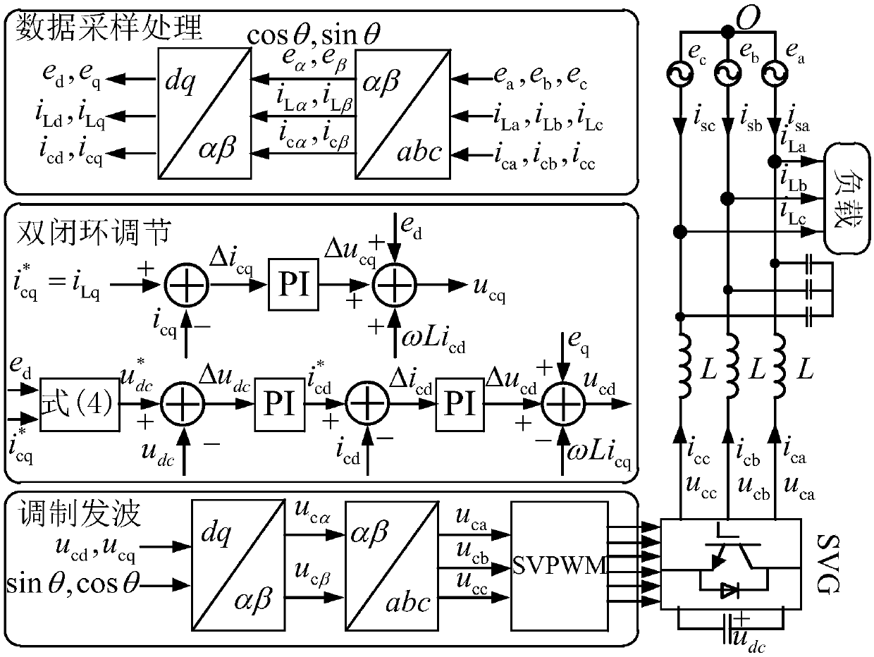
[0036] figure 1 It shows the topological diagram of the SVG main circuit directly connected to the power grid in the prior art. Such as figure 1 As shown, this embodiment is described by taking the static var generator directly connected to the grid to compensate the reactive power of the load as an example.

[0037] The DC side voltage variable control method applied to the static var generator of the present invention is carried out according to the following steps:

[0038] Step 1. Collect the grid voltage, load current, compensation current and DC side voltage in the three-phase static coordinate system at the output end of the static var generator. The specific collection method is the prior art, not the focus of the present invention, therefor...


PUM


Abstract

The invention discloses a DC-side voltage variable control method applied to a static var generator (SVG). A reactive compensation current required to be sent out by the SVG is determined according toa load reactive power current detected in real time, and minimum DC-side voltage conforming to a phase voltage modulation rule is further obtained. A current ring employs direct current control undera dq-coordinate system, a modulation voltage of the SVG under a three-phase static coordination system is obtained by coordinate conversion, a switch sequence is generated, a power device is driven,and control of the SVG is completed. The DC-side voltage is flexibly regulated according to the detected load reactive power current, the SVG is expected to run under relatively high modulation degreeall the way when different load reactive powers are compensated, the DC-side voltage utilization ratio is improved, so that high-efficient control of the SVG is achieved.

Description

technical field [0001] The invention belongs to the technical field of electric power control, and relates to a DC side voltage control method applied to a static var generator, in particular to a DC side voltage variable control method applied to a static var generator. Background technique [0002] A Static Var Generator (SVG for short) is a kind of equipment in a flexible alternating current transmission system (FACTS). Due to its advanced control performance and good compensation effect, it has become an ideal reactive power compensation equipment in AC transmission system. The existing SVG control methods are mainly aimed at maintaining a constant DC side and accurately compensating the reactive current of the load. Among them, the DC side voltage control mainly includes two kinds of DC side voltage independent control and DC side voltage constant control. [0003] The DC side voltage independent control method provides an independent DC power supply to the DC side ca...

Claims


Application Information

Patent Timeline
Patent Type & Authority Applications(China)
IPC IPC(8): H02J3/18
CPCH02J3/1842Y02E40/10
Inventor 张守勇姜卫东崔学保杨光王磊柴浩常静静
Owner ANHUI WANHONG ELECTRICAL EQUIP
Learn More