
Substrate transfer chuck and substrate transfer method

A substrate transfer and clamping technology, which is applied in the direction of conveyor objects, semiconductor devices, electrical components, etc., can solve the problems of the position deviation of two substrates, affect the efficiency of the process operation, and the contours are no longer even, so as to improve the position accuracy Effect

Active Publication Date: 2020-01-17
WUHAN CHINA STAR OPTOELECTRONICS SEMICON DISPLAY TECH CO LTD
View PDF4 Cites 0 Cited by
  • Summary
  • Abstract
  • Description
  • Claims
  • Application Information

AI Technical Summary

Problems solved by technology

After the evaporation process of the half-cut substrate is completed, the two half-board substrates need to be spliced ​​together to complete other subsequent processes. The reason is that the positions of the two substrates are easily shifted, and the contours of the two are no longer flush, which cannot meet the positional accuracy requirements of the subsequent process machines for the glass substrates. Manual correction of the position of the substrates is required, which affects the operations of the subsequent processes. efficiency

Method used


Image

  • Substrate transfer chuck and substrate transfer method
  • Substrate transfer chuck and substrate transfer method
  • Substrate transfer chuck and substrate transfer method

Examples


Embodiment Construction

[0027] In order to make the object, technical solution and advantages of the present invention more clear, the present invention will be further described in detail below in conjunction with the accompanying drawings and embodiments. It should be understood that the specific embodiments described here are only used to explain the present invention, not to limit the present invention.

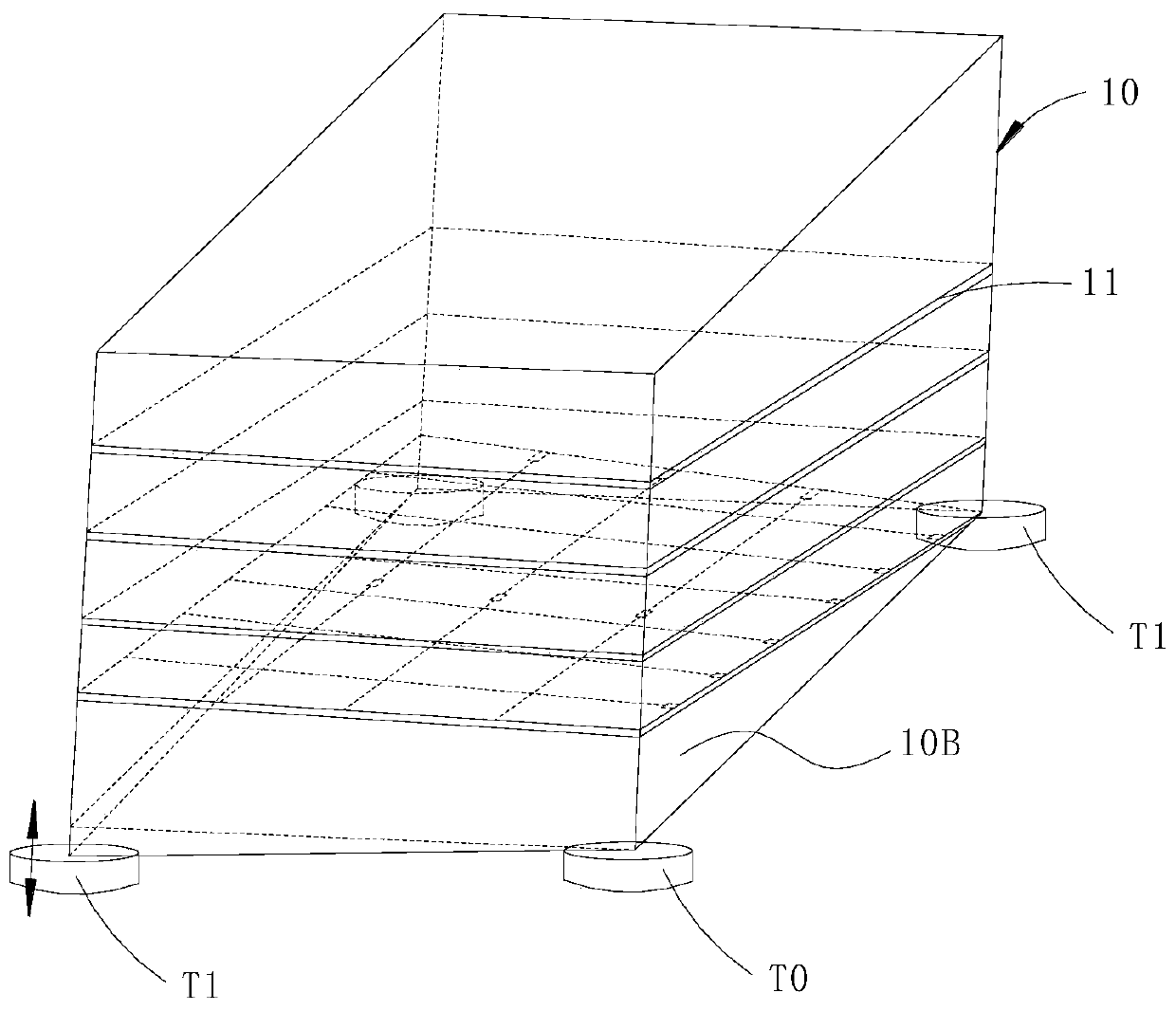
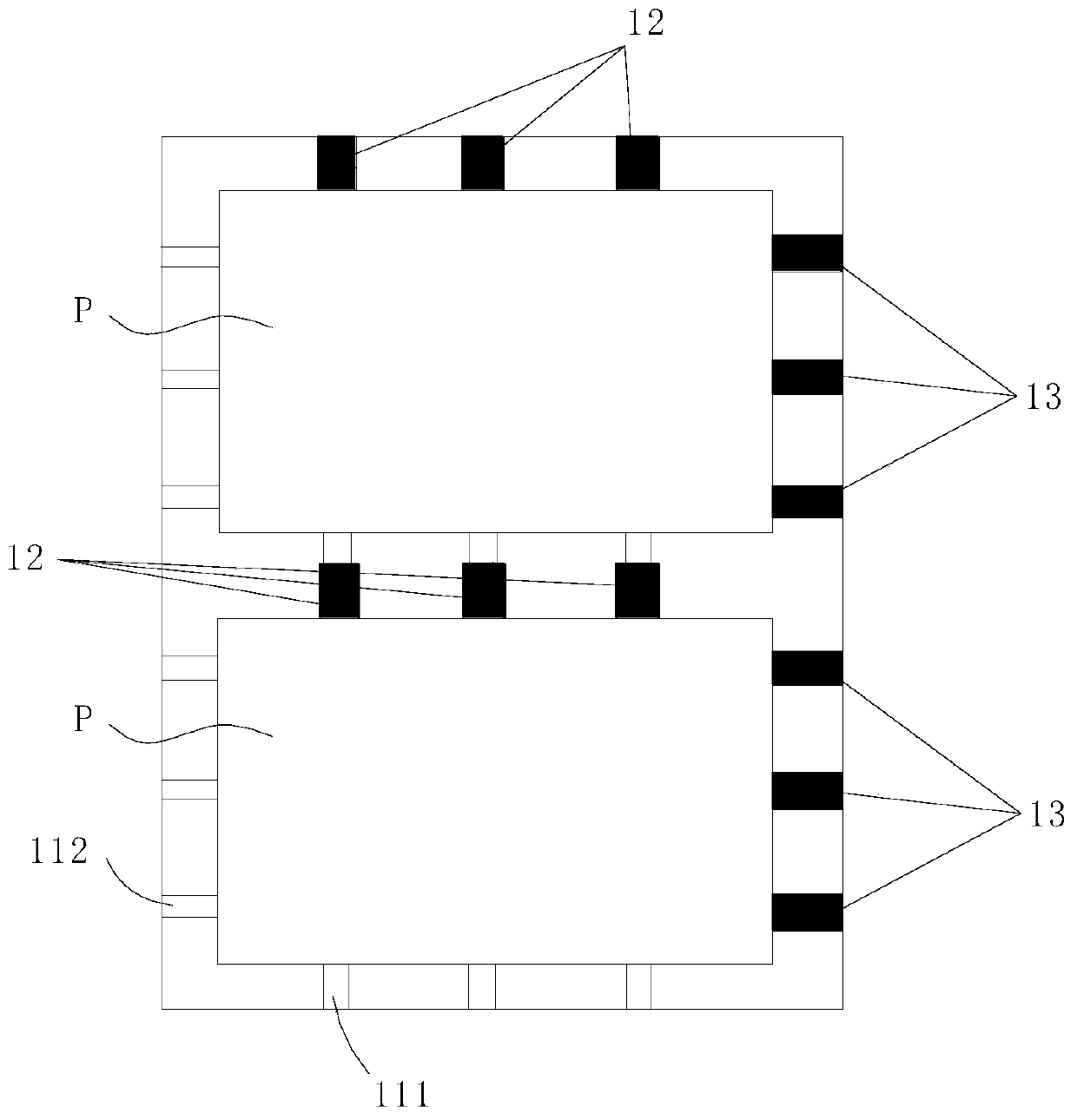
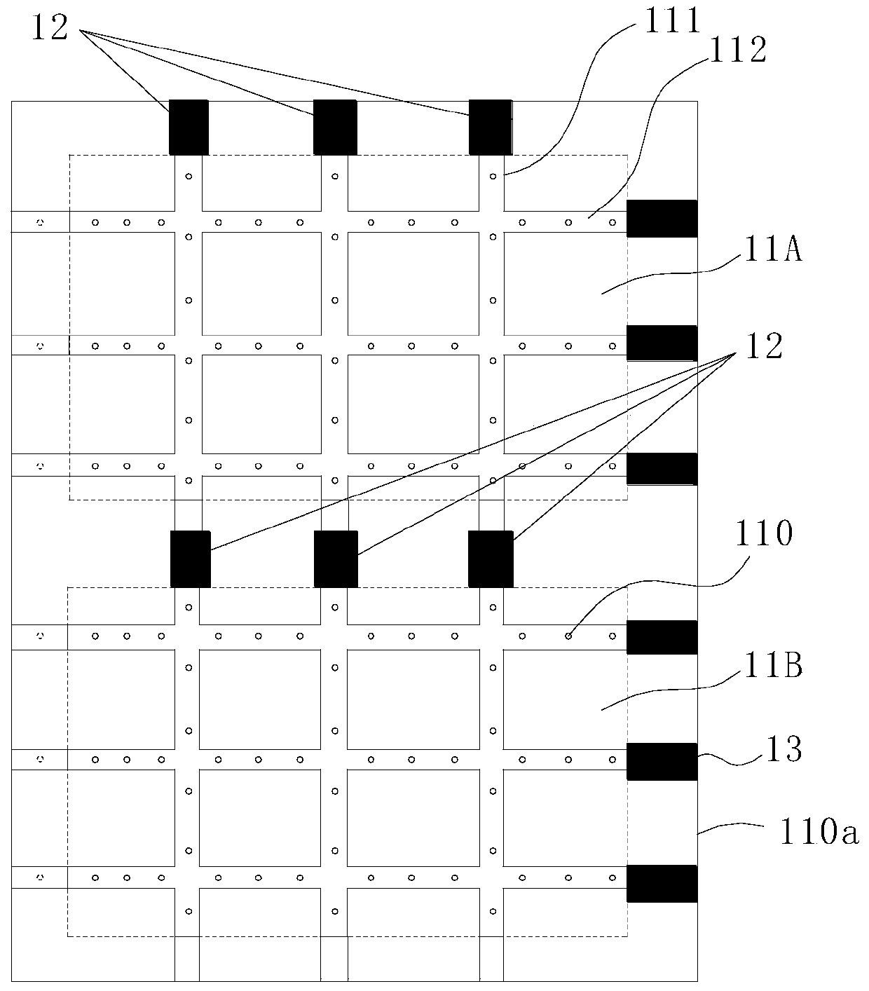
[0028] refer to Figure 1 ~ Figure 3 , the substrate transfer clip of the embodiment of the present invention includes a frame 10, a carrier assembly 11 for carrying the substrate, a first stopper 12 and a second stopper 13, the carrier assembly 11 is fixed in the frame 10, and includes two The first area 11A and the second area 11B of the sheet substrate; a row of linearly arranged first stoppers 12 are respectively provided on the first side of the first area 11A and the second area 11B facing the frame 10, and in the first area 11A, Next to the second side of the second area 11B facing the f...


PUM


Abstract

The invention discloses a clamp for transporting substrates, which includes a frame, a carrying assembly, a first blocking piece and a second blocking piece, the carrying assembly is fixed in the frame, and includes a first area and a second area for carrying two substrates respectively ; A row of linearly arranged first stoppers are respectively provided on the first side of the first area and the second area towards the frame, and a row of linearly arranged first stoppers are respectively provided on the side of the first area and the second area towards the second side of the frame. The second blocking member; the first side is arranged adjacent to the second side, and the bearing assembly is arranged obliquely. The invention also discloses a substrate conveying method. By using an inclined substrate placement method, two substrates are simultaneously carried by the inclined carrier assembly in the frame, the substrates are tilted towards one of the corners, and the two sides with the lowest height of the substrates are controlled by the first stopper and the second stopper The blocking limit ensures that the substrate will not shift during the handling process, and improves the position accuracy of the substrate and the production efficiency of the machine.

Description

technical field [0001] The invention relates to the field of display technology, in particular to a substrate transport clip and a substrate transport method. Background technique [0002] In the AMOLED (Active-matrix organic light emitting diode, active matrix organic light-emitting diode panel) process, the organic light-emitting material needs to be evaporated onto the Array (array) substrate through an evaporation machine. Due to the high price of the evaporation machine and the equipment Due to some limitations of its own characteristics, it is impossible to make larger substrates. [0003] The existing production method is usually to cut the whole substrate in half after the Array substrate is manufactured into two half-board substrates of half size each, and then enter the evaporation machine to complete the evaporation process. After the evaporation process of the half-cut substrate is completed, the two half-board substrates need to be spliced ​​together to complet...

Claims


Application Information

Patent Timeline
Patent Type & Authority Patents(China)
IPC IPC(8): H01L21/677H01L21/68H01L51/56
CPCH01L21/67706H01L21/68H10K59/1201H10K71/00
Inventor 刘思洋
Owner WUHAN CHINA STAR OPTOELECTRONICS SEMICON DISPLAY TECH CO LTD
Learn More