
Minitype speed reducer provided with self-cooling heat sink and specially used for robot and operation method of minitype speed reducer

A technology of heat dissipation device and robot, applied in transmission parts, mechanical equipment, gear lubrication/cooling, etc., can solve the problems of no shock absorption device, loud noise, overheating of the reducer, etc., to prolong the service life, prevent overheating, reduce effect of noise

Pending Publication Date: 2018-03-13
HANGZHOU YUSHEN SPEED REDUCER
View PDF0 Cites 4 Cited by
  • Summary
  • Abstract
  • Description
  • Claims
  • Application Information

AI Technical Summary

Problems solved by technology

[0005] Aiming at the deficiencies of the prior art, the present invention provides a robot-specific miniature reducer with a self-cooling heat dissipation device and its operation method, which solves the problem that the existing microreducer mostly uses gear transmission, has poor stability, and has no cooling device , it is easy to cause overheating of the reducer. At the same time, the existing reducer has no shock absorbing device, the noise is large, and it is inconvenient to use.

Method used


Image

  • Minitype speed reducer provided with self-cooling heat sink and specially used for robot and operation method of minitype speed reducer
  • Minitype speed reducer provided with self-cooling heat sink and specially used for robot and operation method of minitype speed reducer
  • Minitype speed reducer provided with self-cooling heat sink and specially used for robot and operation method of minitype speed reducer

Examples


Embodiment Construction

[0028] The following will clearly and completely describe the technical solutions in the embodiments of the present invention with reference to the accompanying drawings in the embodiments of the present invention. Obviously, the described embodiments are only some, not all, embodiments of the present invention. Based on the embodiments of the present invention, all other embodiments obtained by persons of ordinary skill in the art without making creative efforts belong to the protection scope of the present invention.

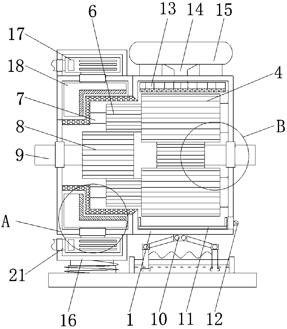
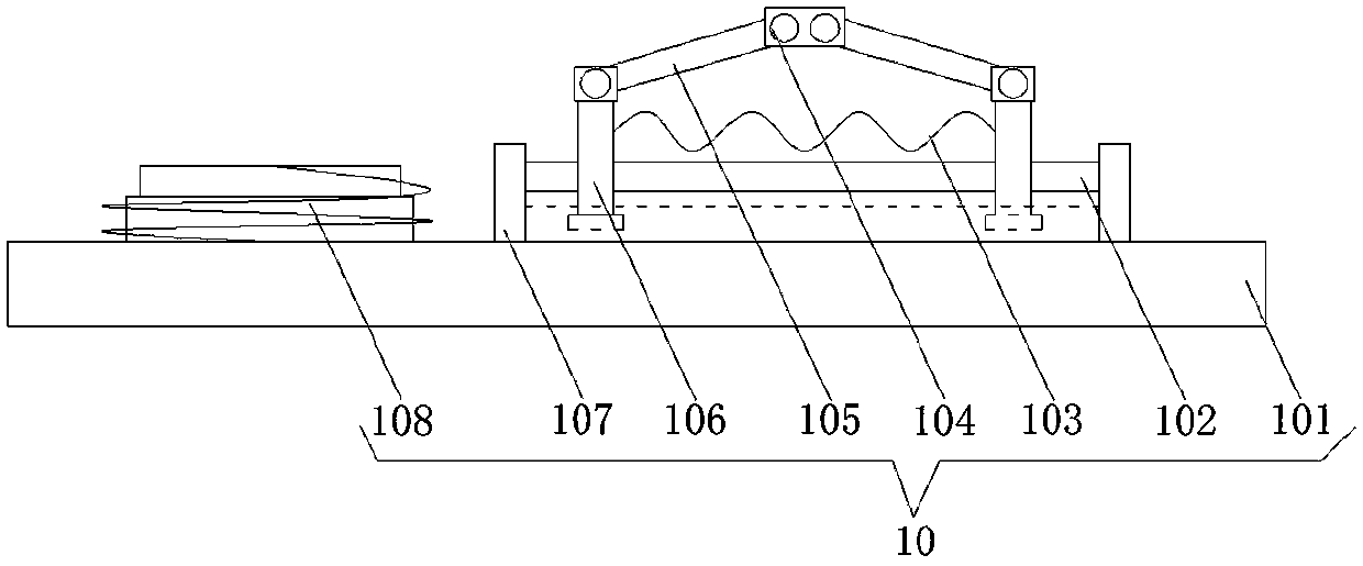
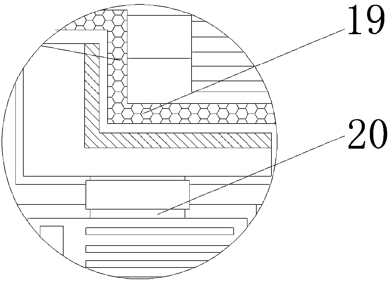
[0029] see Figure 1-4, the present invention provides a technical solution: a special miniature reducer for robots with a self-cooling heat dissipation device, including an outer frame 1, a drive shaft 2 runs through the right side of the outer frame 1, and the drive shaft 2 is located at one end inside the outer frame 1 The first rack 3 is fixedly connected, the top and bottom of the first rack 3 are engaged with the second rack 4, the right end of the secon...


PUM


Abstract

The invention discloses a minitype speed reducer provided with a self-cooling heat sink and specially used for a robot and relates to the technical field of minitype speed reducers. The minitype speedreducer provided with the self-cooling heat sink and specially used for the robot comprises an outer frame. A drive shaft penetrates the right side of the outer frame. The end, located in the outer frame, of the drive shaft is fixedly connected with a first toothed bar, the top and the bottom of the first toothed bar are both engaged with second toothed bars, and the right ends of the second toothed bars are fixedly connected with rotating bases. By means of the minitype speed reducer provided with the self-cooling heat sink and specially used for the robot and the operation method of the minitype speed reducer, the purpose of reducing the speed through toothed rod transmission is achieved, compared with gear transmission, toothed rod transmission is higher in stability, stable in transmission ratio and relatively high in practical performance, damping can be conveniently carried out on the speed reducer, the shake borne by the speed reducer is reduced, the speed reducer is preventedfrom being damaged, moreover, the noise of the speed reducer is effectively lowered, overheating of the speed reducer is prevented, the service life of the speed reducer is effectively prolonged, lubricating oil can be conveniently added to the speed reducer, and the rotation stability of the speed reducer is conveniently improved.

Description

technical field [0001] The invention relates to the technical field of miniature reducers, in particular to a special miniature reducer for robots with a self-cooling heat dissipation device and an operation method thereof. Background technique [0002] The reducer plays the role of matching speed and transmitting torque between the prime mover and the working machine or the actuator. The reducer is a relatively precise machine. The purpose of using it is to reduce the speed and increase the torque. [0003] According to the number of transmission stages, it can be divided into single-stage and multi-stage reducers. According to the shape of the gear wheel, it can be divided into cylindrical gear reducer, bevel gear reducer and conical-cylindrical gear pulley reducer. According to the layout of the transmission, it can be divided into It is divided into expansion type, shunt type and co-axial type reducer. The reducer is an independent component composed of gear transmission...

Claims


Application Information

Patent Timeline
Patent Type & Authority Applications(China)
IPC IPC(8): F16H57/028F16H57/04F16H57/023
CPCF16H57/023F16H57/028F16H57/0416F16H57/045
Inventor 沈立锋沈钊芳陈建华俞兴良宣伟峰王文康项红卫陆建荣
Owner HANGZHOU YUSHEN SPEED REDUCER
Learn More