Preparation method of blade trailing edge bonding angle male mold and blade trailing edge bonding angle preparation method

A blade trailing edge and bonding angle technology, which is applied to household appliances, other household appliances, household components, etc., can solve the problems that cannot meet the irregular trailing edge inner cavity structure, etc.

Active Publication Date: 2020-01-31
GUODIAN UNITED POWER TECH
View PDF6 Cites 0 Cited by
  • Summary
  • Abstract
  • Description
  • Claims
  • Application Information

AI Technical Summary

Problems solved by technology

[0007] The technical problem to be solved by the present invention is to provide a method for preparing a blade trailing edge bonding angle male mold, so that the obtained bonding angle male mold can adapt to the structure of the irregular Guaranteed joint angle, so as to overcome the deficiency that the existing blade trailing edge bonding angle male mold cannot meet the irregular trailing edge cavity structure

Method used


Image

  • Preparation method of blade trailing edge bonding angle male mold and blade trailing edge bonding angle preparation method
  • Preparation method of blade trailing edge bonding angle male mold and blade trailing edge bonding angle preparation method
  • Preparation method of blade trailing edge bonding angle male mold and blade trailing edge bonding angle preparation method

Examples


Embodiment Construction

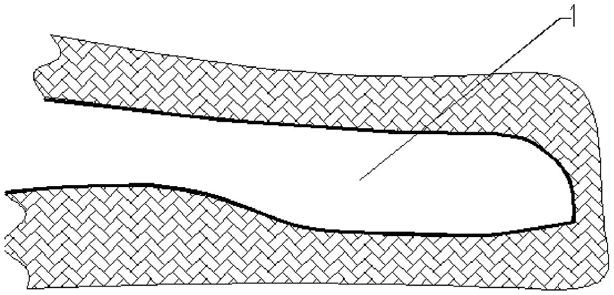
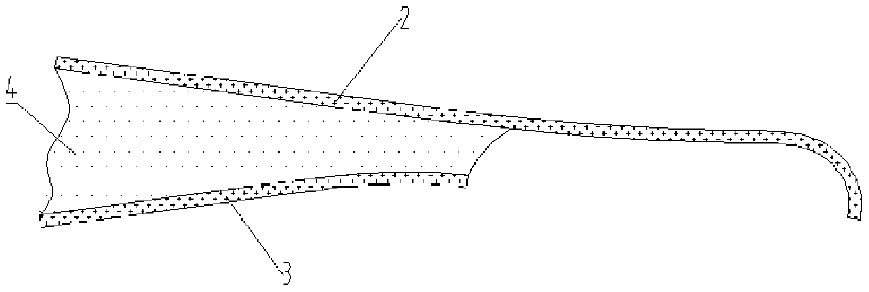
[0037] Refer to attached figure 1 As shown, the present invention is used to prepare a trailing edge bonding angle male mold and a trailing edge bonding angle suitable for an irregular cavity with a large space at both ends and a small space in the middle, which is suitable for the inner cavity of the trailing edge of a wind power blade. From attached figure 1 It can be seen that the bonding angle area 1 of the trailing edge of the blade is an "Ω"-shaped structure with a small mouth and a large cavity. If the bonding angle male mold is prepared according to the conventional bonding angle male mold preparation method, the After it is finished, it will not be able to be removed from the "Ω"-shaped structure with a small mouth and a large cavity. For this shortcoming, refer to the attached figure 2 As shown, the preparation method of the blade trailing edge bonding angle male mold of the present invention is as follows, comprising steps:

[0038] (1) Simulate the bonding angl...


PUM

PropertyMeasurementUnit
thicknessaaaaaaaaaa

Abstract

The invention discloses a blade rear edge bonding angle male die preparing method. The method comprises the steps that three layers of presoaked resin glass fiber cloth are arranged on the SS face shell rear edge bonding area; three layers of presoaked resin glass fiber cloth are arranged on the PS face shell rear edge bonding area, and the glass fiber cloth is away from a PS face shell boss by acertain distance; after the presoaked resin galas fiber cloth is cured, a bonding agent is arranged on the PS face shell glass fiber cloth in a blade coating manner, an SS face shell and a PS face shell are subjected to die assembly, then, the glass fiber cloth on the SS face shell and the glass fiber cloth on the PS face shell are bonded into a whole, and then a rear edge bonding angle male die is obtained. The invention further discloses a method for preparing the rear edge bonding angle through the bonding angle male die. Through the arrangement of the glass fiber cloth with the misalignedend portions, a cavity structure of an omega-shaped structure is ingeniously avoided, the bonding angle male die adapts to blade rear cavities different in specification, and taking out is convenient.The prepared rear edge bonding angle is accurate in positioning, the bonding quality is good, and the phenomenon of rich resin is avoided.

Description

technical field [0001] The invention relates to the technical field of blade trailing edge bonding angles, in particular to a method for preparing a blade trailing edge bonding angle male mold and a blade trailing edge bonding angle preparation method. Background technique [0002] At present, when the SS surface shell of the blade is bonded to the PS surface shell, it is necessary to prepare the trailing edge bonding angle at the trailing edge of the blade first, and then scrape the adhesive on the bonding angle to complete the mold clamping bonding. [0003] Since the existing inner cavity of the trailing edge of the wind power blade is a cavity with a large space at both ends and a small space in the middle, if the positive mold is prepared, the mold cannot be taken out after the bonding angle is formed, so the bonding angle of the blade trailing edge is mainly Female mold preparation. There are two ways to prepare the bonding angle by using the male mold: [0004] (1) ...

Claims


Application Information

Patent Timeline
Patent Type & Authority Patents(China)
IPC IPC(8): B29C70/44B29C70/54B29C65/48B29C69/00B29L31/08
CPCB29C65/48B29C69/00B29C70/44B29C70/54B29L2031/082
Inventor 褚景春袁凌黎江王玉红李颖刘伟超周文明柴红梅师俊峰
Owner GUODIAN UNITED POWER TECH
Why Eureka
Try Eureka