


Quick Research
Generate reliable direction feasibility study reports for your R&D in just a few steps.

Technical Q&A
Discover and master advanced knowledge NOW. Basics, ideas, possibilities, all at once.

Find Solutions
As an expert in R&D theories, this can generate solutions to your technical problems instantly.

Evaluate Feasibility
Analyze your overall solution with one click, know your potential R&D risks in advance.

Monitor Landscape
Get weekly tech updates, stay abreast of the latest tech innovations and key insights.
Inner pot of electric rice cooker and electric rice cooker
A technology for electric rice cookers and inner pots, which is applied in cooking utensils, household utensils, applications, etc. It can solve the problems of poor rice movement, sticking pan, poor rice flatness and air bubble holes, etc., and achieves the effect of easy adjustment
- Summary
- Abstract
- Description
- Claims
- Application Information
AI Technical Summary
Problems solved by technology
Method used
Image

Examples
Embodiment 1
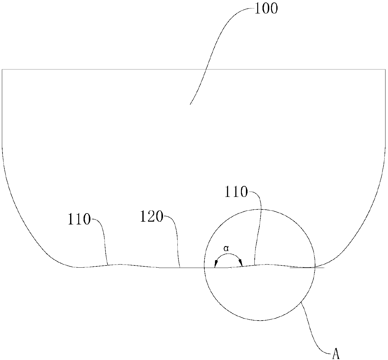
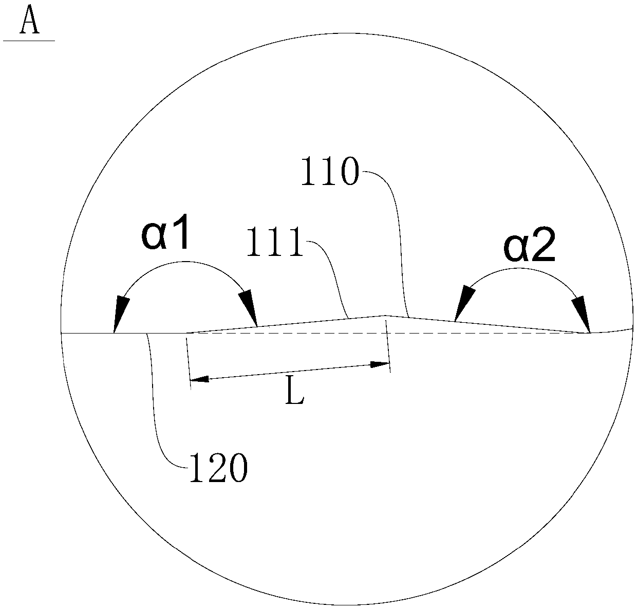
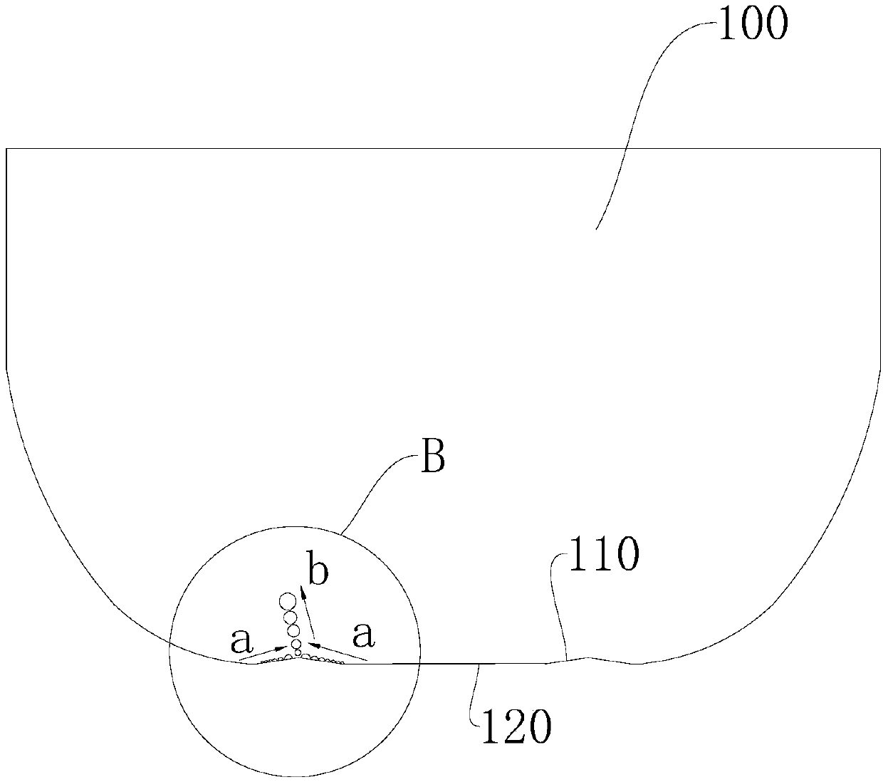
[0070] In this example, if Figure 1-Figure 4 , Figure 14-Figure 15 As shown, the inner surface 120 of the bottom wall of the inner pot 100 is provided with an air bubble escape portion 110 near the side wall of the inner pot 100. The air bubble escape portion 110 is approximately in the shape of a cone, and the top of the cone-shaped air bubble escape portion 110 Formed as a tip, the bus bar 111 is formed as a straight line. Such as figure 2 As shown, the included angles between the peripheral wall of the bubble escape portion 110 and the inner surface 120 of the bottom wall of the inner pot 100 are α1 and α2, wherein the value ranges of α1 and α1 are both 172°-175°, and α1≠α2 . Such as figure 2 and Figure 4 As shown, the air bubbles 200 are directed toward the opening direction of the inner pot 100 along the side wall of the air bubble detachment part 110 (such as Figure 4 Shown by the arrow a) crawling, the maximum distance of the bubbles crawling is L, and L is ...
Embodiment 2
[0074] In this example, if Figure 8 , Figure 10-Figure 11 As shown, the inner surface 120 of the bottom wall of the inner pot 100 is provided with an air bubble escape portion 110 near the side wall of the inner pot 100. The air bubble escape portion 110 is in the shape of a broken line, and the top and bottom of the broken line shaped air bubble escape portion 110 are formed. for the tip. In this way, the moving speed of the air bubbles 200 on the air bubble detachment part 110 can be increased, thereby driving the food in the inner pot 100 to move, thereby not only improving the heating uniformity of the electric rice cooker, but also facilitating the air bubbles 200 to escape from the inner surface 120 of the inner pot 100, It is convenient to control the movement of the bubbles 200 caused by boiling, adjust the flatness of the food in the inner pot 100 and the number of boiling holes, so that the bubbles 200 can escape where needed, thereby improving the performance of ...
PUM
 Abstract
Description
Claims
Application Information
 - R&D Engineer
- R&D Manager
- IP Professional
- Industry Leading Data Capabilities
- Powerful AI technology
- Patent DNA Extraction
Browse by: Latest US Patents, China's latest patents, Technical Efficacy Thesaurus, Application Domain, Technology Topic, Popular Technical Reports.
© 2024 PatSnap. All rights reserved.Legal|Privacy policy|Modern Slavery Act Transparency Statement|Sitemap|About US| Contact US: help@patsnap.com